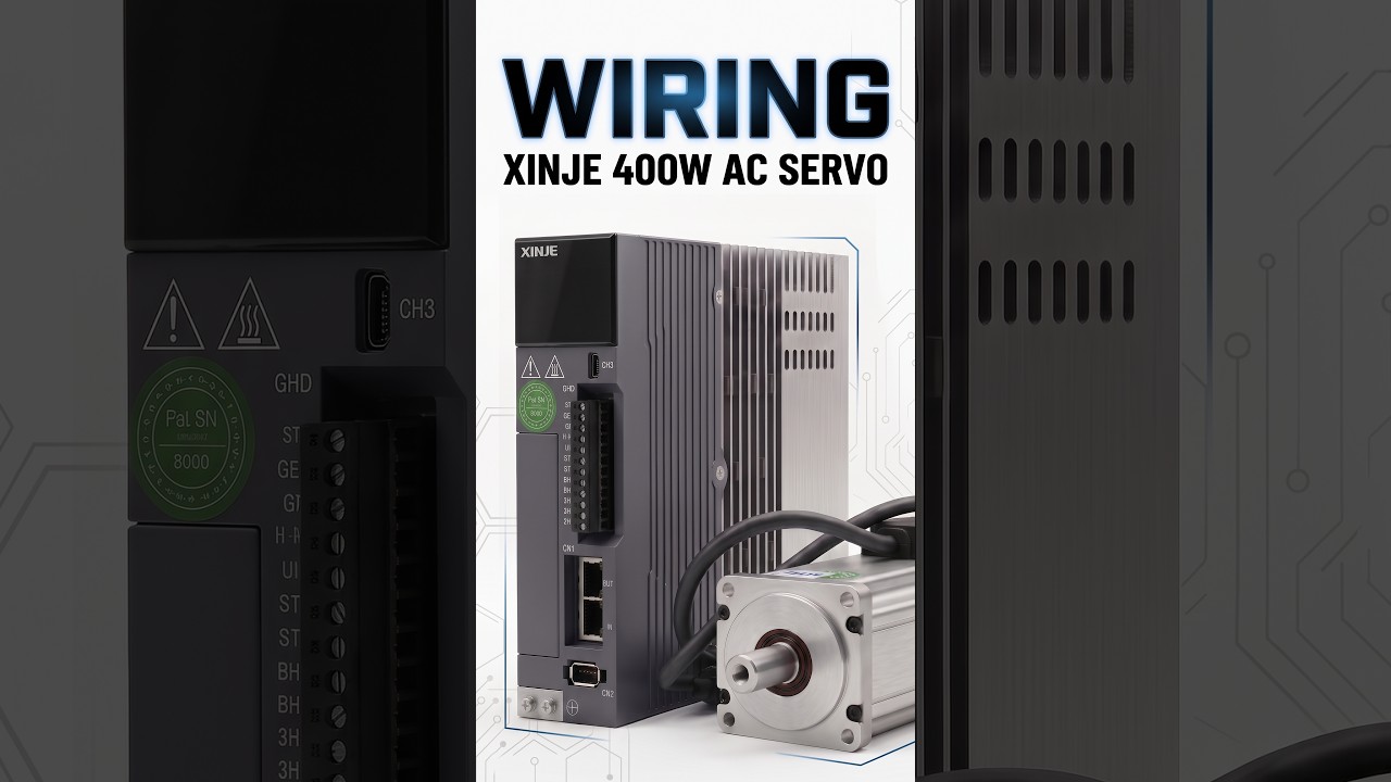
Mastering XINJE 400W AC Servo Wiring for Your CNC System
This article provides an in-depth exploration of CNC system, covering foundational concepts, practical applications, and engineering insights.
Setting up a high-precision motion setup requires accurate wiring, especially when dealing with high-performance drives like the XINJE 400W AC Servo. Proper wiring not only ensures optimal operational efficiency but also protects sensitive electronics within your CNC system. In this step-by-step guide, we will walk you through the essential connections needed to get your XINJE servo drive running smoothly.
Key Components and Safety Precautions
Before beginning the wiring process, ensure you have all necessary hardware ready: the XINJE 400W AC Servo motor, drive unit, main power cables, encoder feedback cable, and the signal control harness. Always prioritize safety by disconnecting all main power sources before handling cables. Additionally, ensure proper grounding for both the drive and motor to eliminate electrical noise and prevent ground loops.
Step-by-Step Wiring Guide
- Main Power Connection: Connect the primary AC power supply to the drive's main power input terminals. Next, connect the motor power lines from the drive’s U, V, and W terminals directly to the corresponding leads on the servo motor.
- Encoder Feedback Wiring: Plug the encoder cable securely into the drive's dedicated encoder port and connect the opposite end to the motor feedback connector. Accurate signal transmission through this feedback loop is crucial for real-time speed and position tracking.
- Control Signals: Wire the digital I/O control harness from your controller to the servo drive's signal port. Proper routing of pulse (PUL) and direction (DIR) signals ensures seamless integration with your CNC system, delivering responsive motion control.
Testing and System Verification
Once all connections are securely fastened, perform a thorough visual inspection to verify correct wire placement and tight terminal contacts. Power on the system to check for any error codes on the drive's LED display. Run a quick jog test at low speed to confirm motor rotation direction and parameter settings.
Following these essential step-by-step wiring instructions helps deliver stable performance, minimal signal interference, and long-term durability for your entire CNC system.


