This post provides information on setting up a Grasshopper definition using Kuka|prc V2 with the Agilus Workcell in the Taubman College Fab Lab.
KUKA|prc is a set of Grasshopper components that provide Procedural Robot Control for KUKA robots (thus the name PRC). These components are very straightforward to use and it's actually quite easy to program the robots using them.
There are five palettes which organize the components. These are:

The Core component takes five inputs. These are:

The settings are organized into pages which you select from along the top edge of the dialog (Settings, Advanced, and Analysis). The dialog is modeless which means you can operate Rhino while it is open. To see the effect of your changes in the viewport click the Apply button. These settings will be covered in more detail later.

Note: The latest revision of Kuka|prc contains a custom robot for the Agilus workcell. It has two output sockets, Mitey and Titey. Simply wire in the robot you intend to use and no more configuration is required.

Mitey
Mitey is the name of the robot mounted in the table. Its base is at 0,0,0. The robot is rotated about its vertical axis 180 degrees. That is, the cable connections are on the right side of the robot base as you face the front of the workcell.

To set up Mitey do the following:
Bring up the Settings dialog by left clicking on KUKA|prc Settings label on the Core component. The dialog presented is shown below:

You specify the X, Y, and Z offsets in the Base X, Base Y, and Base Z fields of the dialog. Again, for Mitey these should all be 0. In order to rotate the robot around the vertical axis you specify 180 in the Base A field. You can see that the A axis corresponds to vertical in the diagram.
Titey
The upper robot hanging from the fixture is named Titey. It has a different X, Y and Z offset values and rotations. Use the settings below when your definition should run on Titey.

Note: These values are all in millimeters.
To set the output directory and file name follow these steps:

That's all you need to do to generate code.
See the topic Taubman College Agilus Workcell Operating Procedure for details on how to get the code onto the robot and run it.
You specify these start and end position values in the Settings of the Core. Bring up the settings dialog and choose the Advanced page.
Under the Start / Endposition section you enter the axis values for A1 through A6. This begs the questions "how do I know what values to use?".

You can read these directly from the physical robot pendant. That is, you jog the robot into a reasonable start position and read the values from the pendant display. Enter the values into the dialog. Then do the same for the End values. See the section Jogging the Robot in topic Taubman College Agilus Workcell Operating Procedure.
You can also use KUKA|prc to visually set a start position and read the axis values to use. To do this you wire in the KUKA|prc Axis component into the Core component. You can "virtually jog" the robot to a specific position using a setup like this:

Then simply read the axis values from your sliders and enter these as the Start Position or End Position.
Another way is to move the simulation to the start point of the path. Then read the axis values from the Analysis output of the Core Settings dialog. You can see the numbers listed from A01 to A06. Jot these down, one decimal place is fine. Then enter them on the Advanced page.


See the post Robot Motion Analysis Using Light for a visual display of the motion types.
Note: The information in this section contains material excerpted from the KUKA documentation.

You use the right-click menu on this component to choose the interpolation settings. Choose No Interpolation or C_PTP.

You use the right-click menu on this component to choose the interpolation settings. Choose No Interpolation, C_DIS or C_VEL.

You use the right-click menu on this component to choose the interpolation settings. Choose No Interpolation, C_DIS or C_ORI.
CDIS: A distance in mm can be assigned to the interpolation setting CDIS. In this case the controller leaves the path, at the earliest, when the distance from the end point falls below the value in CDIS.
CVEL: A percentage value can be assigned to the interpolation setting CVEL. This value specifies the percentage of the programmed velocity at which the approximate positioning process is started, at the earliest, in the deceleration phase of the motion. The path will be altered in order to maintain the specified percentage of the programmed velocity.
CORI: An orientation percentage can be assigned to the interpolation setting CORI. In this case, the path is left, at the earliest, when the dominant orientation angle (swiveling or rotation of the longitudinal tool axis) falls below the angle percentage, defined in CORI.
CPTP: The following is taken from the Kuka Expert Programming Guide: For the purposes of PTP approximate positioning, the controller calculates the distances the axes are to move in the approximate positioning range and plans velocity profiles for each axis which ensure tangential transition from the individual instructions to the approximate positioning contour. Uhhh... say what now?! How about this: The greater the value of CPTP, the more the path is rounded!
See the post Robot Motion Analysis Using Light for a visual display of the motion types.
KUKA|prc is a set of Grasshopper components that provide Procedural Robot Control for KUKA robots (thus the name PRC). These components are very straightforward to use and it's actually quite easy to program the robots using them.
Terminology
Before we begin discussing KUKA|prc it's important to clarify some terminology that will be used in this topic.- Work Cell: All the equipment needed to perform the robotic process (robot, table, fixtures, etc.)
- Work Envelope: All the space the robot can reach.
- Degrees of Freedom: The number of movable motions in the robot. To be considered a robot there needs to be a minimum of 4 degrees of freedom. The Kuka Agilus robots have 6 degrees of freedom.
- Payload: The amount of weight a robot can handle at full arm extension and moving at full speed.
- End Effector: The tool that does the work of the robot. Examples: Welding gun, paint gun, gripper, etc.
- Manipulator: The robot arm (everything except the End of Arm Tooling).
- TCP: Tool Center Point. This is the point (coordinate) that we program in relation to.
- Positioning Axes: The first three axes of the robot (1, 2, 3). Base / Shoulder / Elbow = Positioning Axes. These are the axes near the base of the robot.
- Orientation Axes: The other joints (4, 5, 6). These joints are always rotary. Pitch / Roll / Yaw = Orientation Axes. These are the axes closer to the tool.
Rhino File Setup
When you work with the robots using KUKA|prc your units in Rhino must be configured for the Metric system using millimeters. The easiest way to do this is to use the pull-down menus and select File > New... then from the dialog presented chose "Small Objects - Millimeters" as your template.The KUKA|prc User Interface
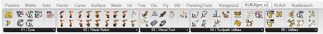
When installed KUKA|prc has a user interface (UI) much like other Grasshopper plug-ins. The UI consists of the palettes in the KUKA|prc menu.
There are five palettes which organize the components. These are:
- 01 | Core: The main Core component is here (discussed below). There are also the components for the motion types (linear, spline, etc.).
- 02 | Virtual Robot: The various KUKA robots are here. We'll mostly be using the the KUKA gelis KR6-10 R900 component as those are what's used in the Agilus workcell.
- 03 | Virtual Tools: Approach and Retract components are here (these determine how the robot should move after a toolpath has completed). There are also components for dividing up curves and surfaces and generating robotic motion based on that division.
- 04 | Toolpath Utilities: The tools (end effectors) are here. We'll mostly be using the Custom Tool component.
- 05 | Utilities: The components dealing with input and outputs are stored here. These will be discussed later.
KUKA|prc CORE
The component you always use in every definition is called the Core. It is what generates the KUKA Robot Language (KRL) code that runs on the robot. It also provides the graphical simulation of the robot motion inside Rhino. Everything else gets wired into this component.The Core component takes five inputs. These are:
- SIM - This is a numeric value. Attach a default slider with values from 0.00 to 1.00 to control the simulation.
- CMDS - This is the output of one of the KUKA|prc Command components. For example a Linear motion command could be wired into this socket.
- TOOL - This is the tool (end effector) to use. It gets wired from one of the Tool components available in the Virtual Tools panel. Usually you'll use the KUKA|prc Custom Tool option and wire in a Mesh component will show the tool geometry in the simulation.
- ROBOT - This is the robot to use. The code will be generated for this robot and the simulation will graphically depict this robot. You'll wire in one of the robots from the Virtual Robot panel. For the Agilus Workcell you'll use the Agilus KR6-10 R900 component.
- COLLISION - This is an optional series of meshes that define collision geometry. Enable collision checking in the KUKA|prc settings to make use of this. Note that collision checking has a large, negative impact on KUKA|prc performance.
- GEO: This is the geometry of the robot at the current position - as a set of meshes. You can right-click on this socket and choose Bake to generate a mesh version of the robot for any position in the simulation. You can use this for renderings for example.
- ANALYSIS: This provides detailed analysis of the simulation values. This has to be enabled for anything to appear. You enable it in the Settings dialog, Advanced page, Output Analysis Values checkbox. Then use the Analysis component from the Utilities panel. For example if you wire a Panel component into the Axis Values socket you'll see all the axis values for each command that's run.

Settings
The gray KUKA|prc Settings label at the bottom of the Core component gives you access to its settings. Simply left click on the label and the dialog will appear.The settings are organized into pages which you select from along the top edge of the dialog (Settings, Advanced, and Analysis). The dialog is modeless which means you can operate Rhino while it is open. To see the effect of your changes in the viewport click the Apply button. These settings will be covered in more detail later.

Basic Setup
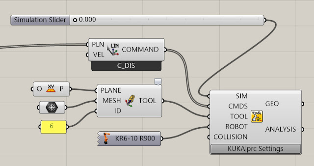
There is a common set of components used in nearly all definitions for use with the Agilus Workcell. Not surprisingly, these correspond to the inputs on the Core component. Here is a very typical setup:
- SIM SLIDER: The simulation Slider goes from 0.000 to 1.000. Dragging it moves the robot through all the motion specified by the Command input. It's often handy to drag the right edge of this slider to make it much wider than the default size. This gives you greater control when you scrub to watch the simulation. You may also want to increase the precision from a single decimal point to several (say 3 or 4). Without that precision you may not be able to scrub to all the points you want to visualize the motion going through.
You can also add a Play/Pause component. This lets you simulate without dragging the time slider. - CMDS: The components which gets wired into the CMDS slot of the Core is really the heart of your definition and will obviously depend on what you are intending the robot to do. In the example above a simple Linear Move component is wired in.
- TOOL: We normally use custom tools with the Agilus Workcell. Therefore a Mesh component gets wired into the KUKA|prc Custom Tool component (labelled TOOL above). This gets wired into the TOOL slot of the Core. The Mesh component points to a mesh representation of the tool drawn in the Rhino file. See the section below on Tool orientation and configuration.
- ROBOT: The robots we have in the Agilus Workcell are KUKA KR6 R900s. So that component is chosen form the Virtual Robots panel. It gets wired into the ROBOT slot of the Core.
- COLLISION: If you want to check for collisions between the robot and the workcell (table) wire in the meshes which represent the workcell. As noted above this has a large negative impact on performance so use this only when necessary.
Robot Position and Orientation
The Agilus workcell has two robots named Mitey and Titey. Depending on which one you are using you'll need to set up some parameters so your simulation functions correctly. These parameters specify the location and orientation of the robot within the workcell 3D model.Note: The latest revision of Kuka|prc contains a custom robot for the Agilus workcell. It has two output sockets, Mitey and Titey. Simply wire in the robot you intend to use and no more configuration is required.
If you don't have the latest version, see below for how to set them up.
Mitey
Mitey is the name of the robot mounted in the table. Its base is at 0,0,0. The robot is rotated about its vertical axis 180 degrees. That is, the cable connections are on the right side of the robot base as you face the front of the workcell.

To set up Mitey do the following:
Bring up the Settings dialog by left clicking on KUKA|prc Settings label on the Core component. The dialog presented is shown below:

You specify the X, Y, and Z offsets in the Base X, Base Y, and Base Z fields of the dialog. Again, for Mitey these should all be 0. In order to rotate the robot around the vertical axis you specify 180 in the Base A field. You can see that the A axis corresponds to vertical in the diagram.
- Base X: 0
- Base Y: 0
- Base Z: 0
- Base A: 180
- Base B: 0
- Base C: 0
Titey
The upper robot hanging from the fixture is named Titey. It has a different X, Y and Z offset values and rotations. Use the settings below when your definition should run on Titey.

Note: These values are all in millimeters.
- Base X: 1102.5
- Base Y: 0
- Base Z: 1125.6
- Base A: 90
- Base B: 180
- Base C: 0
Code Output
The purpose of KUKA|prc is to generates the code which runs on the robot controller. This code is usually in the Kuka Robot Language (KRL). You need to tell KUKA|prc what directory and file name to use for its code output. Once you've done this, as you make changes in the UI, the output will be re-written as necessary to keep the code up to date with the Grasshopper definition.To set the output directory and file name follow these steps:
- Bring up the Settings dialog via the Core component.
- On the main Settings page, enter the project filename and choose an output directory. Note: See the ? button in the dialog for recommendations on the filename (which characters to avoid).

That's all you need to do to generate code.
See the topic Taubman College Agilus Workcell Operating Procedure for details on how to get the code onto the robot and run it.
Start Position / End Position
When you work with robots there are certain issues you always have to deal with:- Reach: Can the robot's arms reach the entire workpiece?
- Singularities: Will any joint positions result in singularities? (See below for more on this topic)
- Joint Limits: During the motion of the program will any of the axes hit their limits?
You specify these start and end position values in the Settings of the Core. Bring up the settings dialog and choose the Advanced page.
Under the Start / Endposition section you enter the axis values for A1 through A6. This begs the questions "how do I know what values to use?".

You can read these directly from the physical robot pendant. That is, you jog the robot into a reasonable start position and read the values from the pendant display. Enter the values into the dialog. Then do the same for the End values. See the section Jogging the Robot in topic Taubman College Agilus Workcell Operating Procedure.
You can also use KUKA|prc to visually set a start position and read the axis values to use. To do this you wire in the KUKA|prc Axis component into the Core component. You can "virtually jog" the robot to a specific position using a setup like this:

Then simply read the axis values from your sliders and enter these as the Start Position or End Position.
Another way is to move the simulation to the start point of the path. Then read the axis values from the Analysis output of the Core Settings dialog. You can see the numbers listed from A01 to A06. Jot these down, one decimal place is fine. Then enter them on the Advanced page.

Initial Posture
Related to the Start Point is the Initial Posture setting. If you've set the Start Position as above and are still seeing motion (like a big shift in one of the axis to reorient) try the As Start option. This sets the initial posture to match the start position.
Motion Types
KUKA|prc provides several motion types. These are Point to Point, Linear, Circular, or Spline. This section presents the differences between the motions and the components and settings used to get them in your definitions.See the post Robot Motion Analysis Using Light for a visual display of the motion types.
PTP: Point to Point
The robot guides the TCP along the fastest path to the end point. The fastest path is generally not the shortest path and is thus not a straight line. As the motions of the robot axes are rotational, curved paths can be executed faster than straight paths. The exact path of the motion cannot be predicted.
You get this motion type by using the KUKA|prc PTP Movement component.

You get this motion type by using the KUKA|prc PTP Movement component.
You use the right-click menu on this component to choose the interpolation settings. Choose No Interpolation or C_PTP.
LIN: Linear
The robot guides the TCP at a defined velocity along a straight path to the end point. This path is predictable.
You get this motion type by using the KUKA|prc Lin Movement component.

You get this motion type by using the KUKA|prc Lin Movement component.
You use the right-click menu on this component to choose the interpolation settings. Choose No Interpolation, C_DIS or C_VEL.
CIRC: Circular
The robot guides the TCP at a defined velocity along a circular path to the end point. The circular path is defined by a start point, auxiliary point and end point.
You get this motion type by using the KUKA|prc Cir Movement component.

You get this motion type by using the KUKA|prc Cir Movement component.
You use the right-click menu on this component to choose the interpolation settings. Choose No Interpolation, C_DIS or C_ORI.
SPLINE: Smooth Spline
The robot will move along the positions in a smooth spline motion.

You get this motion type by using the KUKA|prc Spline Movement component.


You get this motion type by using the KUKA|prc Spline Movement component.
You use the right-click menu on this component to choose the interpolation settings. Choose No Interpolation, C_DIS or C_ORI.
All the movement types are affected by interpolation settings. These can be turned off or enabled via right-click menus on the movement components - linear movement options are shown below:

The values used for interpolation are set on the Advanced page of the Core Settings:

Approximate positioning is activated by entering values for CDIS, CVEL, or CORI. The larger the values in CDIS, CVEL, or ORI, the earlier the approximate positioning begins. In certain circumstances, the system may shorten approximate positioning, but will never lengthen it.
The approximate positioning motion is automatically generated by the controller. To make approximate positioning possible, the value for Advance Run must be at least 1.
Approximate Positioning - Interpolation Settings
In order to increase velocity, points for which exact positioning is not necessary can be approximated. The robot essentially takes a shortcut.All the movement types are affected by interpolation settings. These can be turned off or enabled via right-click menus on the movement components - linear movement options are shown below:

The values used for interpolation are set on the Advanced page of the Core Settings:

Motions with Approximate Positioning
Interpolation affects the way the robot smooths movement. Without interpolation, the robot will briefly stop at each position. The interpolation values affect at which point the robot starts to interpolate – either at a certain distance from the target point, or at a certain percentage between the start and target point. Generally, a higher value leads to smoother movement but less accuracy.Approximate positioning is activated by entering values for CDIS, CVEL, or CORI. The larger the values in CDIS, CVEL, or ORI, the earlier the approximate positioning begins. In certain circumstances, the system may shorten approximate positioning, but will never lengthen it.
The approximate positioning motion is automatically generated by the controller. To make approximate positioning possible, the value for Advance Run must be at least 1.
CDIS: A distance in mm can be assigned to the interpolation setting CDIS. In this case the controller leaves the path, at the earliest, when the distance from the end point falls below the value in CDIS.
CVEL: A percentage value can be assigned to the interpolation setting CVEL. This value specifies the percentage of the programmed velocity at which the approximate positioning process is started, at the earliest, in the deceleration phase of the motion. The path will be altered in order to maintain the specified percentage of the programmed velocity.
CORI: An orientation percentage can be assigned to the interpolation setting CORI. In this case, the path is left, at the earliest, when the dominant orientation angle (swiveling or rotation of the longitudinal tool axis) falls below the angle percentage, defined in CORI.
CPTP: The following is taken from the Kuka Expert Programming Guide: For the purposes of PTP approximate positioning, the controller calculates the distances the axes are to move in the approximate positioning range and plans velocity profiles for each axis which ensure tangential transition from the individual instructions to the approximate positioning contour. Uhhh... say what now?! How about this: The greater the value of CPTP, the more the path is rounded!
See the post Robot Motion Analysis Using Light for a visual display of the motion types.
Tool Setup
Correct setup of tools is essential. The dimension and orientation of the tool needs to be set in KUKA|prc as well as on the robot controller. The values need to match - and a mismatch is a very common source of problems. By matching what is meant is an ID number is assigned to the tool in KUKA|prc and the same values must be set in the corresponding tool ID on the robot controller.
Understanding tool setup is really understanding the coordinate system they are based on. The coordinate system uses the right-hand rule. Using your right-hand (!) position your fingers perpendicular to one another as shown below. The X axis is in the direction of the thumb, the Y axis is the index finger, and the Z axis is along the middle finger.

The default orientation of this coordinate system is aligned on the tool plate as follows: The +X axis come directly perpendicular to the tool plate. The +Z axis is perpendicular and goes up. The +Y axis is perpendicular to the other two.

This orientation of this coordinate system can be easily changed in the tool definition. In all the samples used below the tool is defined with +Z coming out from the tool plate.
As an example here's the Axis Teach Tool. It shows the orientation of the robot using Red (X axis), Green (Y axis) and Blue (Z axis) visually. If you jog in Tool Mode you can see the robot slide along red, green or blue dowel axes.

Here's how you'd 3D model this tool in Rhino. The tool is located at world 0,0,0, with +Z going up. World 0,0,0 is right at the base of the robot:


Note that the tool mount plate needs to be modeled as part of the tool. It is a cylinder, 10.5mm (0.413") thick and 88.9mm (3.5") in diameter.

Note that the tool needs to be a mesh. A single mesh - so use the Mesh command to convert the NURBS geometry to a mesh. Then if necessary use MeshBooleanUnion to generate a single mesh of all the parts.

Note how the tooltip shows the resulting transformation you use at the physical robot. These numbers are simply the values are required to change the coordinate system from the default (+X perpendicular to the tool face plate) to your desired one (+Z perpendicular to to the tool face plate). A simple rotation about the Y axis does this. Thus the tool definition is a rotation about B (Y axis) of 90 degrees.

In this case an offset from the world origin is used. In the teach tool example, you want the origin to be at the center of rotation for the three axes. This is 20mm above the base of the tool. In this way, when you rotate the tool in Tool Mode, it will revolve around the center of each axis.

You can see the resulting offset you enter at the robot, again, using the tool tip. Note that Z is now 20mm.

You enter these numbers X 0, Y 0, Z 20, A 0, B 90, C 0 into the tool ID of 6 using the physical robot pendant. See the section Installing a Tool in Taubman College Agilus Workcell Operating Procedure for details on how to enter these values.


Download the Rhino and Grasshopper Files


Download the Rhino and Grasshopper Files


Download the Rhino and Grasshopper Files
(Coming as the Winter 2016 semester progresses...)
(Coming as the Winter 2016 semester progresses...)
(Coming as the Winter 2016 semester progresses...)
KUKA robots with 6 degrees of freedom have 3 different singularity positions.
Understanding tool setup is really understanding the coordinate system they are based on. The coordinate system uses the right-hand rule. Using your right-hand (!) position your fingers perpendicular to one another as shown below. The X axis is in the direction of the thumb, the Y axis is the index finger, and the Z axis is along the middle finger.

The default orientation of this coordinate system is aligned on the tool plate as follows: The +X axis come directly perpendicular to the tool plate. The +Z axis is perpendicular and goes up. The +Y axis is perpendicular to the other two.

This orientation of this coordinate system can be easily changed in the tool definition. In all the samples used below the tool is defined with +Z coming out from the tool plate.
Tool Mesh
When you 3D model the tool do so at the world origin and such that the tool Z axis is aligned with world Z. In the case of the Agilus workcell the origin is at the base of the robot, Mitey.As an example here's the Axis Teach Tool. It shows the orientation of the robot using Red (X axis), Green (Y axis) and Blue (Z axis) visually. If you jog in Tool Mode you can see the robot slide along red, green or blue dowel axes.


Note that the tool needs to be a mesh. A single mesh - so use the Mesh command to convert the NURBS geometry to a mesh. Then if necessary use MeshBooleanUnion to generate a single mesh of all the parts.

Custom Tool-Plane Setup
Here's how you setup the the tool inside Kuka|prc. Use the Custom Tool-Plane component (available in the Virtual Tool panel). Use the WorldXY as the plane. Use a Mesh component to retrieve the single mesh. Use an Integer or Panel component to provide the tool ID number. These all get wired into the Custom Tool - Plane.Note how the tooltip shows the resulting transformation you use at the physical robot. These numbers are simply the values are required to change the coordinate system from the default (+X perpendicular to the tool face plate) to your desired one (+Z perpendicular to to the tool face plate). A simple rotation about the Y axis does this. Thus the tool definition is a rotation about B (Y axis) of 90 degrees.

In this case an offset from the world origin is used. In the teach tool example, you want the origin to be at the center of rotation for the three axes. This is 20mm above the base of the tool. In this way, when you rotate the tool in Tool Mode, it will revolve around the center of each axis.

You can see the resulting offset you enter at the robot, again, using the tool tip. Note that Z is now 20mm.

You enter these numbers X 0, Y 0, Z 20, A 0, B 90, C 0 into the tool ID of 6 using the physical robot pendant. See the section Installing a Tool in Taubman College Agilus Workcell Operating Procedure for details on how to enter these values.
Working with Planes
See the topic Working with Planes in Kuka |prc for details on using planes in your definitions.Example Definitions
The following examples are typical use cases for using the robots.Following a Curve - Fixed Orientation
This is a simple example where the tool is moved with a constant orientation through the control points of a curve. This example is the robot moving a tool through a maze.

Download the Rhino and Grasshopper Files
Following a Ruled Surface - Hot Wire Cutting
This example drives a hot wire cutting tool along a surface. The hot wire is a straight line. When you move a straight line through space the resulting surface which is swept is called a Ruled Surface. This particular definition keeps the tool in a constant orientation (the Y axis, along the axis of the cut, is constant).
Download the Rhino and Grasshopper Files
Multi-Part Assembly: Stacking
This example introduces the notion of multi-part assembly using a gripper tool. The robot is used for stacking blocks to recreate a parametric wall. The lofted surface guides the stacking and an optional gray scale image provides additional corbelling and rotation to the blocks. This definition used digital IO to open and close the pneumatic gripper.

Download the Rhino and Grasshopper Files
Following a Curve - Tangent Orientation
This example also follows a curve - but the tool is rotated so it is tangent to the curve. An example of this in use is cutting with a knife. In such cases you want the cutting blade to rotate with the curve.(Coming as the Winter 2016 semester progresses...)
Painting
This example has the robot following a series of curves in a fixed orientation. The code however measures the distance covered. When a goal distance is covered, the robot automatically returns to a source location to "get more paint". Then to motion picks up where it left off and continues to apply paint. This example uses the Grasshopper Python component.(Coming as the Winter 2016 semester progresses...)
Surfacing
This example has the robot following along a surface. Included in the definition is the ability to gradually step down to the surface (similar to a roughing pass when removing material with a CNC router).(Coming as the Winter 2016 semester progresses...)
Singularities
A singularity results from the collinear alignment of two or more robot axes which causes unpredictable robot motion or unexpected velocities in the motion. For this reason, motion paths that make the robot pass near singularities should be avoided.KUKA robots with 6 degrees of freedom have 3 different singularity positions.
- Overhead singularity
- Extended position singularity
- Wrist axis singularity


