Designing complex 3D models for precision manufacturing often starts in CAD software like SolidWorks. If you are learning computer-aided design to prepare parts for machining, understanding fundamental 3D features is essential. In this practical CNC tutorial guide, we will explore the SolidWorks Swept Base/Boss feature and how it helps you build intricate, smooth geometry ideal for digital fabrication.
What is the SolidWorks Swept Base Tool?
The Swept Base (or Swept Boss) feature allows designers to create 3D solids by driving a 2D profile sketch along a defined guide path. Unlike standard extrusions that only extend linearly, a sweep can follow complex curves, splines, and multi-directional trajectories. Whether you are modeling custom piping, ergonomic handles, or curved structural frames, mastering this tool is a vital step in any foundational CNC tutorial for 3D modeling.
Step-by-Step Guide to Creating Your First Sweep
Draw the Path Sketch: Begin by sketching a line, arc, or spline on a plane to define the exact path your profile will follow.
Draw the Profile Sketch: Create the cross-sectional shape (such as a circle, square, or custom contour) on a plane perpendicular to the start of your path.
Execute the Swept Boss Feature: Open the Swept Base/Boss tool from the Features tab, select your profile and path in the property manager, and generate the 3D solid.
Optimizing CAD Sweeps for CNC Machining
Creating geometry in SolidWorks is only half the process; your model must also be easy to machine. When preparing your digital models as part of a complete CNC tutorial workflow, always consider cutting tool geometry:
Mind the Tool Radius: Avoid excessively tight interior curves that standard end mills cannot physically reach.
Maintain Smooth Tangency: Ensure path segments are tangent to prevent sudden directional shifts that could trigger machine chatter or tool wear.
Check Wall Thickness: Keep structural walls uniform along the sweep to prevent part distortion during machining.
By mastering the SolidWorks Swept Base feature with manufacturing in mind, you can seamlessly bridge the gap between initial digital concepts and physical CNC production. Practice creating different profiles and paths today to elevate your design capabilities!
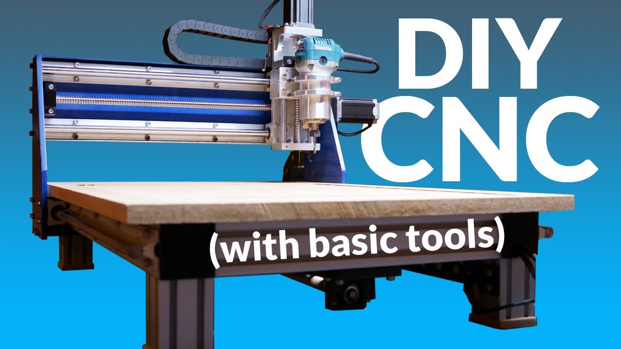
Have you ever dreamed of owning a CNC machine but found the price tag of commercial units intimidating? While cheap online desktop kits exist, they are often small, underpowered, and lack the rigidity required for serious projects. Building your own DIY CNC router from scratch might seem like a daunting engineering task, but as many makers have proven, it is entirely possible even if you only have limited tools and no prior experience.
Empower your workshop by building a custom DIY CNC router machine from the ground up.
What is a CNC Machine and How Does it Work?
CNC stands for Computer Numeric Control. Essentially, it is a milling machine operated by a computer that drives motors to execute precise and repeatable machining tasks. While humans might struggle with consistency, a CNC machine excels at it.
The system works by interpreting instructions called G-Code. The computer sends these codes to stepper motors, which differ from regular DC motors because they move in tiny increments called "steps." These motors are linked to a linear motion system—such as ball screws or belts—converting rotational movement into precise lateral motion across three or more axes (X, Y, and Z).
Key Design Choices for a Rigid DIY CNC
When engineering a custom desktop CNC router, two factors dictate success: power and rigidity. Without a rigid frame, the machine will flex, ruining your cuts or preventing you from machining harder materials like aluminum. Key component selections include:
Drive System: A screw-driven system (using ball screws) is highly preferred over belt-driven designs due to superior rigidity and force transmission.
Frame Materials: Utilizing heavy-duty 6060 aluminum extrusions provides an excellent strength-to-weight ratio while remaining affordable. Solid aluminum plates (e.g., 3/8-inch or 1/2-inch thick) work best for heavy-stress structural components like the Gantry side plates.
Linear Rails: Supported linear rails on the X and Y axes ensure smooth, deflection-free travel.
Spindle Choice: The Makita RT0701C router is a popular, cost-effective, and widely reliable spindle choice for desktop builds.
The Hardware Construction: Building with Basic Tools
You don't need an industrial machine shop to build a high-quality CNC. A successful build can be accomplished using standard workshop tools: a basic benchtop drill press, a miter saw (which can cut aluminum surprisingly smoothly), files, digital calipers, and a metric drill and tap set.
Axis Component
Common Dimensions / Spec
Function
Y-Axis Rails
800 mm Supported Rails
Moves the entire Gantry frame assembly forward and backward.
X-Axis Rails
600 mm Supported Rails
Carries the Z-axis carriage left and right along the Gantry.
Z-Axis Assembly
Pre-built Linear Unit
Controls the vertical movement and depth of the router spindle.
To ensure perfect alignment with limited tools, a smart trick is to bolt identical plates (like the Gantry sides) together while drilling and filing them. This guarantees they end up exactly the same size and shape, preventing structural binding later on.
The Electronics and Brains of the Machine
The movement relies on strong stepper motors, such as high-torque Nema 23 motors, paired with individual digital stepper drivers and a dedicated power supply (usually 36V).
To orchestrate the motion, an Arduino Uno running open-source GRBL firmware serves as the budget-friendly intermediary control board. It translates commands from your computer software (like Universal G-Code Sender) into step and direction signals for the drivers.
Crucial Build Tip: Electromagnetic Interference (EMI)
Standard low-cost cables can act as antennas, picking up electronic noise from the power draw under heavy loads. This often triggers false positives in your limit switches, causing the machine to stop mid-job. To avoid this frustration, always use shielded microphone cables for motor and switch wiring, and route them tidily using drag chains.
Testing, Calibration, and Enclosures
Once fully assembled, the final step involves prepping the spoil board—a sacrificial MDF surface fitted with threaded inserts to clamp down your workpieces. Using a wide facing bit to flatten the surface ensures the bed is perfectly parallel to your spindle tip.
Additionally, constructing a clear acrylic and wood enclosure is highly recommended. A CNC router flings dust and wood chips everywhere, so an enclosure keeps your workspace pristine while dramatically dampening the loud whine of the router spindle.
Watch the Full DIY CNC Build Process
Building a custom DIY CNC router requires patience and can easily take months of planning, tweaking, and calibrating. However, the reward of seeing a machine you built with your own hands cleanly carve complex 3D wood designs or precision aluminum parts makes the entire engineering journey worth it.
Introduction to CNC Machining and the Power of DIY
CNC stands for Computer Numeric Control. In basic terms, it is a milling machine operated by a computer that drives motors to execute precise and highly repeatable machining operations. Compared to standard human handiwork, a CNC machine is capable of movements that are far more accurate, rigid, and consistent. By interpreting digital instructions known as G-code, stepper motors move the cutting tool across three or more axes (X, Y, and Z) to precisely shape various materials.
While industrial or pre-built desktop CNC machines can be incredibly expensive or lack the rigid structure required for heavy-duty tasks, building your own DIY CNC router allows you to customize the dimensions, ensure maximum rigidity, and optimize the overall performance within a reasonable budget.
Key Engineering Principles: Rigidity and Component Selection
When designing a reliable CNC router, power and structural rigidity are the two most critical factors. High rigidity ensures the machine can cut through hard wood or even light-duty aluminum without vibrating or losing precision. To achieve this, several key structural design choices must be implemented:
Screw-Driven System: Utilizing ball screws instead of belt-driven systems provides significantly higher torque, precision, and zero backlash under heavy loads.
Supported Linear Rails: Implementing heavy-duty supported linear rails on the X and Y axes provides smooth lateral movements while effectively handling mechanical stress.
Aluminum Extrusions and Solid Plates: Constructing the main frame with 6060 aluminum extrusions offers a lightweight yet rigid foundation. Crucial structural parts, such as the Gantry side plates, should be machined from solid aluminum plates (e.g., 3/8-inch or 1/2-inch thickness) to maintain vertical alignment.
Spindle Selection: A reliable and widely available router, such as the Makita RT0701C, serves as an excellent affordable spindle option for desktop setups.
The Mechanical and Electronic Assembly Process
Building a CNC router from scratch involves precise manual crafting and accurate electronics wiring. Here is the step-by-step breakdown of the assembly framework:
1. Mechanical Fabrication and CAD Design
Before buying components, using a CAD program like Autodesk Fusion 360 allows you to model every dimension accurately. Once the 800mm rails for the y-axis and 600mm rails for the x-axis are aligned, the solid aluminum plates must be cut, drilled, and tapped using metric M5/M6 bolts and t-slot nuts. A replaceable MDF spoil board is then mounted on top of the mainframe and flattened using a facing bit to ensure it remains perfectly parallel to the cutting tool.
2. Motor Integration and Electronic Control Box
To drive the lateral motion systems, high-torque Nema 23 stepper motors (e.g., 425 oz-in) are paired with dedicated stepper drivers and a 36-volt power supply unit. An Arduino Uno running open-source GRBL firmware functions as the primary intermediary control board, converting signals from the computer into physical pulse/direction steps for the motors.
3. Reducing Signal Noise and Wire Management
One major issue during heavy machining is electromagnetic interference (EMI). It is highly recommended to use shielded microphone cables for all motor and limit switch lines to prevent false positives that can trigger random emergency stops. Organizing these cables inside dynamic drag chains protects the wiring from entering the toolpath of the spinning router bit.
Testing, Tuning, and Enclosure Additions
Once the electronics are enclosed and the firmware is properly configured via software like Universal Gcode Sender (UGS), initial calibration involves running basic 2D letter carves before attempting complex 3D wood modeling. Additionally, building a dedicated acrylic and wooden enclosure is vital. The enclosure successfully contains wood dust and aluminum chips from creating a massive mess while significantly dampening the loud acoustic noise produced by the spindle motor.