Computer Numerical Control (CNC) machinery has revolutionized modern woodworking. What once required years of master craftsmanship can now be achieved with precision and consistency right in your home workshop. Whether you are an absolute beginner or an experienced maker looking to upgrade your workflow, starting with the right DIY CNC projects is key to mastering your machine.
In this comprehensive beginner's guide, we explore popular starter projects that help you understand feed rates, toolpaths, and material settings without overwhelming your process.
Watch the Full Beginner Tutorial
Top Beginner CNC Woodworking Projects
1. Custom Wooden Signs and Lettering
Wooden signage is one of the easiest and most profitable ways to learn CNC routing. By practicing basic V-carving techniques, you gain confidence in setting z-zero offsets and managing different wood grain densities.
2. Decorative Coasters and Trivets
Small-scale projects like drink coasters allow you to experiment with 2D profile cutting, pocketing, and inlaying without wasting large amounts of raw lumber. They make excellent practice pieces and personalized gifts.
3. Modular Storage Solutions
Building small organizers, tray inserts, or tool holders helps you learn tight tolerance joints such as finger joints and dadoes. This is essential for moving on to larger furniture builds in the future.
Essential Tips for CNC Beginners
Start with Softwoods or MDF: Practice your designs on inexpensive materials before cutting into expensive hardwoods like walnut or oak.
Double-Check Workholding: Ensure your material is firmly clamped or vacuum-sealed to prevent movement during routing.
Prioritize Safety: Always wear eye protection and maintain proper dust collection to keep your shop clean and clear.
Introduction: The Revolution of Computer Numerical Control
In the era of Industry 4.0, digital manufacturing has transformed the way we transform ideas into physical objects. Computer Numerical Control (CNC) machining stands at the heart of this manufacturing revolution. By combining computer-aided design with automated precision cutting, CNC machines make it possible to produce highly complex, custom parts with unparalleled accuracy and consistency.
Watch: How CNC Machines Work in Industry 4.0
How the CNC Manufacturing Process Works
The journey from a digital concept to a physical workpiece involves several integrated stages. Here is a step-by-step breakdown of how a modern CNC system operates:
1. Digital CAD/CAM Design
Everything begins with a 3D model created using Computer-Aided Design (CAD) software. Once the geometry is defined, Computer-Aided Manufacturing (CAM) software translates the design into precise toolpaths and G-code instructions that the machine controller understands.
2. Automated Tooling and Material Setup
Raw stock material—whether aluminum, steel, wood, or plastics—is securely clamped onto the machine bed. The CNC machine automatically selects the necessary end mills, drills, or cutting inserts based on the programmed operations.
3. High-Precision Subtractive Machining
Unlike additive manufacturing (such as 3D printing), CNC is a subtractive process. The cutting tool rapidly rotates and moves along multiple axes (typically 3-axis, 4-axis, or 5-axis) to chip away excess material until the exact final shape is achieved.
Conclusion
Understanding CNC machining is essential for modern engineers, designers, and hobbyists alike. As Industry 4.0 continues to evolve, smart automation and advanced CNC technology will further blur the line between digital imagination and physical creation.
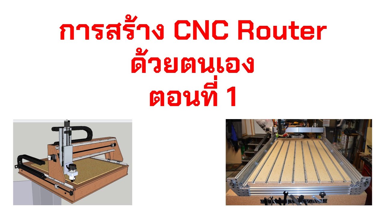
Learn the essential steps and concepts to assemble your first DIY CNC router like a professional maker.
Introduction to DIY CNC Routing
Building your own CNC (Computer Numerical Control) router is one of the most rewarding projects for woodworkers, makers, and hobbyists. A DIY CNC machine gives you precise control over cutting, carving, and engraving various materials like wood, acrylics, and soft metals without paying a premium for industrial machines.
Whether you want to start a custom woodworking business or simply expand your workshop capabilities, understanding the basic structure and mechanics of a CNC router is key to building a reliable tool.
Watch: DIY CNC Router Build Guide (Part 1)
Check out the video below for a comprehensive walk-through on setting up and assembling a DIY CNC router from scratch:
Key Components You Need for a DIY CNC Build
Before assembling your machine, it is crucial to familiarize yourself with the core hardware components that make up a CNC system:
Frame & Rails: Aluminum extrusions or heavy-duty steel provide stability and reduce vibration during cutting.
Linear Motion & Drive Systems: Lead screws, ball screws, or timing belts move the axes smoothly.
Stepper Motors: Drive the X, Y, and Z axes to precise locations based on G-code instructions.
Spindle / Router: The cutting head that spins the bit to shape or cut materials.
Control Board & Drivers: Translates commands from your computer into electrical signals for the motors.
Steps to Ensure a Successful Build
1. Square Your Frame
Precision is everything in CNC machining. Ensure that all corners of your frame are perfectly square during assembly to prevent inaccuracies during operation.
2. Plan Cable Management
Loose wires can snag during high-speed movements. Use drag chains (cable carriers) to keep stepper motor cables and power wires neatly organized.
3. Test Movement Before Cutting
Always perform dry runs without a bit installed to test motor direction, homing switches, and travel limits before cutting actual materials.
Computer Numerical Control (CNC) milling has revolutionized precision manufacturing across industries worldwide. By converting digital designs into intricate physical parts, CNC milling machines offer unprecedented accuracy, speed, and repeatability. Whether producing aerospace components or custom automotive parts, understanding the fundamental mechanics of CNC milling is essential for engineers, makers, and industry professionals alike.
Watch: How It Works - CNC Milling Machine
How CNC Milling Works
At its core, CNC milling is a subtractive manufacturing process. It begins with a solid block of material—known as a workpiece—and removes excess layers using rotary cutting tools until the final geometry is achieved. The entire operation is guided by G-code, a programmed instruction set generated from 3D CAD models.
Key Components of a CNC Milling System
The Spindle: Holds and rotates the cutting tool at high speeds to shave off material.
Axis Controllers: Move the workpiece or spindle precisely along multiple directions (X, Y, and Z axes).
Coolant System: Reduces heat friction during heavy cutting and removes metal chips from the cutting zone.
Control Unit: The computer interface that reads the code and controls all machine movements.
Conclusion
CNC milling stands as a cornerstone of modern manufacturing technology. Its ability to automate complex subtractive cutting with high precision reduces human error and drastically accelerates production cycles. As technology continues to evolve, multi-axis CNC machines and automated workflows will continue to drive innovation across advanced engineering disciplines.
Understanding CNC Machining in Modern Manufacturing
Computer Numerical Control (CNC) machining is a fundamental manufacturing process that has revolutionized how precision parts are produced across industries worldwide. From aerospace and automotive to medical devices and custom prototyping, CNC technology enables high accuracy, efficiency, and repeatability that manual operation simply cannot match.
In this guide, we explore the core principles of CNC machining, how pre-programmed software guides industrial tools, and why this technology remains essential for modern manufacturing.
Watch: What is CNC Machining and How Does it Work?
How Does the CNC Process Work?
At its core, CNC machining is a subtractive manufacturing process. It starts with a solid block of raw material—such as metal, plastic, or wood—and removes excess material using cutting tools until the final part shape is achieved.
1. CAD & CAM Design
The workflow begins with a 3D digital model created in Computer-Aided Design (CAD) software. This model is then converted into G-code via Computer-Aided Manufacturing (CAM) software, providing instructions for machine movements, tool speeds, and feed rates.
2. Machine Setup and Execution
Once loaded into the CNC machine controller, the automated cutting tools (such as drills, mills, or lathes) follow the digital instructions with extreme precision, achieving tolerances down to thousandths of an inch.
Key Advantages of CNC Technology:
High Precision & Accuracy: Consistent results for complex geometric shapes.
Material Versatility: Compatible with metals, polymers, composites, and hardwoods.
Summary
CNC machining combines digital design precision with automated mechanical power, making it an indispensable part of modern product development and industrial manufacturing. Whether you are creating single prototypes or scaling high-volume production, understanding CNC fundamentals helps optimize production efficiency and product quality.
If you are brand new to the world of CNC machining, creating your very first custom wooden sign can feel a bit overwhelming. From choosing the right design software and setting up toolpaths to selecting the proper router bits, there are several steps you need to get right. Fortunately, this comprehensive, beginner-friendly guide walks you through the entire process of making a professional-looking "EXIT" sign with a custom arrow, step-by-step.
Whether you want to make signs for your home, workshop, or as personalized gifts, mastering these fundamental CNC woodworking skills will give you the confidence to tackle more complex projects in the future.
Step 1: Layout & Design in VCarve Pro
Every successful CNC project starts inside the CAD/CAM software. For this project, we are using VCarve Pro. Here is how to configure your workspace:
Job Type: Single-sided project.
Material Dimensions: 12.5 inches (X-axis) by 11 inches (Y-axis) with a thickness of 3/4 inch.
Z-Zero Position: Set to the material surface.
XY Datum Position: Set to the center of the project.
Use the Text tool to type your message (e.g., "EXIT" in Times New Roman) and use the drawing handles to scale and rotate your design easily. To draw the arrow, combine a basic rectangle with a three-sided polygon, aligning them to a center reference line, and use the interactive cut tool to trim the inner lines into a single solid arrow vector.
Step 2: Choosing Your Bits and Toolpaths
Since the sign features large engraved areas, we will use a two-step engraving process (a clearing pass and a finishing pass):
The Clearing Pass: Check the "flat depth" box and set it to 0.1 inches. Use a 1/4-inch (0.25") end mill. This clears out the bulk of the flat bottom areas inside the letters and arrow. Make sure to use a raster cut along the X-axis so the tool moves with the wood grain, which drastically reduces the need for sanding later.
The Finishing Pass: Use a 90-degree V-bit to carve out the sharp corners and detailed edges where the larger end mill couldn't reach.
Save these two toolpaths separately since they require different router bits on your CNC machine.
Watch the Detailed Video Tutorial:
Step 3: Edge Routing and Painting the Blank
Cut your wood stock to size using a table saw. To give the sign a premium look, route a decorative edge around it using a Roman Ogee bit on your router table.
Pro Tip: To prevent tear-out (chipping on the corners), always route the end grain edges first before routing along the grain sides!
Once routed, apply two to three coats of white outdoor paint to seal all faces and edges, sanding lightly between coats. Let it dry completely overnight.
Step 4: Applying Oramask 813 and Carving
To get perfectly crisp paint lines, apply Oramask 813 stencil film to the painted surface. Use a plastic scraper to burnish the mask firmly onto the wood, pushing out any air bubbles. Trim the mask along the edge of the Roman Ogee profile with a sharp utility knife.
Secure the masked board to your CNC bed, center your spindle over your designated workspace center point, set your X and Y axes to zero, and probe your Z-axis height. Run the 90-degree V-bit finishing pass first, then switch to the 1/4-inch end mill (re-zeroing your Z-axis for the new bit length) to run the clearing pass.
Step 5: Sealing, Painting, and Peeling
Because wood is porous, paint can easily bleed underneath the masking stencil. To prevent this, coat the freshly carved wood channels with a layer of water-based polyurethane first. Once dry, this layer seals the wood pores completely.
Next, use a small brush to fill the carved cavities with your secondary paint color (e.g., dark blue). Applying two coats of the blue paint ensures rich and uniform coverage. Once the paint is dry, carefully peel away the Oramask using a weeding tool or utility knife to reveal incredibly sharp, professional, bleed-free paint lines!
Final Thoughts
Creating custom signs is one of the most rewarding projects you can do as a CNC beginner. It teaches you the basics of design, correct toolpathing, the importance of masking stencils like Oramask, and wood preparation techniques. Mount a sawtooth hanger on the back, and your beautiful custom-made wooden sign is ready to hang!
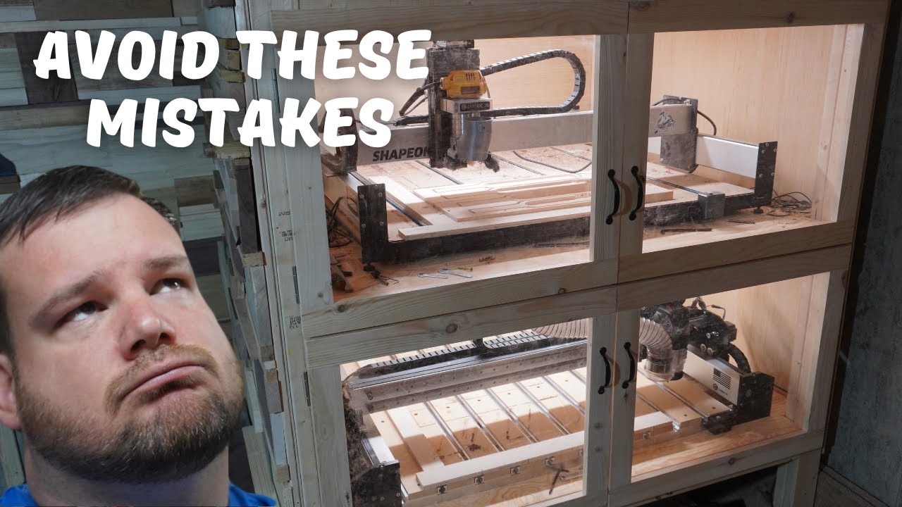
Getting started with a desktop CNC router is an exciting journey, but the learning curve can be incredibly steep. It is easy to make simple errors that not only ruin your workpieces but also waste your time, break expensive bits, and cost you money. In this guide, we dive into five of the most common mistakes beginners make when starting out with CNC machining and provide actionable solutions to ensure you get clean cuts and keep your workshop running smoothly.
1. Running Your Spindle Speed Too Fast
Many beginners assume that a faster spindle speed equals better and faster cutting. However, running your router or spindle at maximum RPM (such as 28,000 RPM on a typical palm router) is often unnecessary and can actually ruin your tools and materials.
The Issue: High speeds create excessive friction, leading to heat buildup that burns your wood and dulls your cutting edges rapidly.
The Goal: You want to produce clean wood chips, not fine sawdust. If your machine is producing dust and smoke, your speeds are not dialed in correctly.
The Fix: Slow down your spindle speed (RPM) or increase your feed rate. Keep in mind that larger cutters and v-bits generally require slower RPM settings to work efficiently.
2. Poor Workholding Choices
Keeping your material securely locked down to the wasteboard is crucial for accuracy and safety. Choosing the wrong clamping method can lead to shifted parts or, worse, broken bits.
The Clamp Hazard: Using bulky clamps that protrude above your workpiece is a recipe for disaster, as your CNC gantry or spindle can easily crash into them.
Alternative 1 (Screws): If you are cutting out nested parts from a larger sheet, simply screwing the waste areas directly into your wasteboard keeps everything flush and safe.
Alternative 2 (Double-Sided Tape): For delicate or thin pieces where you cannot use screws, high-quality double-sided carpet tape provides a strong, low-profile hold without interfering with the path of your tool.
3. Becoming Paralyzed by "What to Make"
Many makers purchase a desktop CNC with the goal of starting a woodworking business or selling crafts. However, getting stuck in the product development phase can prevent you from ever starting.
The Trap: Analyzing the market to the point where you are too afraid to cut your first project because you worry it won't sell.
The Solution: Start by creating things that interest you personally. Building your skills, understanding how materials behave, and mastering your CAD/CAM software on projects you enjoy will naturally pave the path toward commercial-grade designs.
4. Bad End Mill Selection
Walking into the world of CNC routers means facing hundreds of different router bit configurations. Buying random bits without knowing their specific purposes can get expensive quickly.
Upcut vs. Downcut Bits: Upcut bits pull wood fibers upward (leaving a clean bottom but frayed top edge), while downcut bits push chips downward (giving you an incredibly clean top finish).
V-Bits: Essential for signs, detailed carving, and lettering.
The Core Starter Trio: Instead of buying massive, expensive kits, you only need three basic bits to cover 99% of beginner projects: an up/down cut compression bit, a v-bit, and a bowl/tray bit.
5. Neglecting Dust Collection
It is easy to prioritize the machine assembly and skip dust management to save a quick buck. However, running a CNC router without dust collection will quickly cover your entire workshop in fine, hazardous wood dust.
The Impact: Aside from the health hazards of breathing in airborne particulates, wood dust can settle on your machine's linear rails, lead screws, and belts, leading to premature wear and tracking errors.
The Budget Fix: You do not need a massive, dedicated industrial dust collector. A standard shop vac hooked up to a basic 3D-printed or commercial dust boot on your spindle will collect the vast majority of chips right at the source.
Conclusion
Mastering your desktop CNC router takes patience, practice, and a willing attitude to learn from minor setbacks. By regulating your spindle speeds, securing your workpieces safely, starting with simple designs, choosing the right end mills, and keeping your work area clean with a shop vac, you will bypass the costliest beginner mistakes and fast-track your way to successful CNC projects.
Optimizing industrial automation through precise state synchronization.
In the world of precision manufacturing, the gap between software logic and hardware execution can lead to costly errors. Achieving a seamless System Design Alignment requires a robust methodology to ensure that your CNC machine states reflect the digital twin or the control architecture accurately.
1. Define the Finite State Machine (FSM)
The first step in any CNC Machine States integration is defining a clear Finite State Machine. Every transition—from IDLE to RUNNING, or ERROR to RESET—must be mapped within the system design documentation.
Idle State: Ready for commands, no active movement.
Processing State: Active execution of G-code.
Interrupted State: E-stop or manual pause triggered.
2. Implementing the Synchronization Layer
To align the machine with the system design, a middleware or communication protocol (like OPC UA or MQTT) is essential. This layer ensures that the System Design receives real-time telemetry from the CNC controller.
Key Tip: Always use Keep-Alive signals to ensure the system design knows the machine hasn't just entered a "hidden" state due to connection loss.
3. Validation and Error Handling
Alignment isn't complete without rigorous validation. You must simulate "Illegal State Transitions" to see how the system design handles unexpected machine behavior. This proactive approach minimizes downtime and enhances safety protocols in Industrial Automation.
Conclusion
Aligning CNC Machine States with System Design is not just a technical requirement; it is a strategic advantage. By following a structured FSM approach and ensuring robust communication, manufacturers can achieve higher transparency and efficiency on the shop floor.
In the era of Smart Manufacturing, simply collecting data isn't enough. To truly optimize production, manufacturers must understand the direct correlation between CNC events and OEE loss factors. This guide explores the methodology of transforming raw machine data into actionable insights to boost manufacturing efficiency.
Understanding the OEE Framework
Overall Equipment Effectiveness (OEE) is calculated based on three main categories: Availability, Performance, and Quality. Each category is impacted by specific "Loss Factors" that can be traced back to CNC machine events.
Step-by-Step Correlation Methodology
1. Data Acquisition from CNC Controllers
The first step involves extracting real-time signals from the CNC controller (such as Fanuc, Siemens, or Heidenhain). Key events include:
Cycle Start/Stop: Indicates active production.
Alarm Codes: Specific triggers for unplanned downtime.
To analyze OEE Loss Factors, we must map CNC events to the "Six Big Losses":
CNC Event Type
OEE Category
Specific Loss Factor
Emergency Stop / Alarm
Availability
Unplanned Downtime
Setup Mode / Tool Change
Availability
Setup and Adjustments
Reduced Feed Rate
Performance
Reduced Speed
Short Stops / Idling
Performance
Small Stops
3. Time-stamping and Contextualization
Correlation requires precise time-stamping. By aligning the CNC event log with the production schedule, you can identify if a "Machine Stop" was a planned break or an unexpected OEE availability loss.
Benefits of Data Correlation
By implementing a systematic Method to Correlate CNC Events, factories can achieve:
Root Cause Analysis: Don't just see that the machine stopped; know why it stopped based on the alarm code.
Real-time Bottleneck Identification: Spot performance drops as they happen.
Predictive Maintenance: Use frequent minor alarms to predict major component failures.
"Turning raw CNC data into OEE intelligence is the bridge between a traditional workshop and a true Digital Twin environment."
Conclusion
Mastering the correlation between machine behavior and productivity metrics is essential for any Industry 4.0 journey. Start by capturing clean data, mapping it to standard OEE losses, and using those insights to drive continuous improvement on the shop floor.
In the era of Industry 4.0, achieving high OEE Accuracy is a top priority for manufacturers. However, relying on raw data directly from CNC machines can be misleading. To ensure your metrics reflect reality, you need a robust Method to Validate Real-Time CNC Data.
Why Data Validation is Critical for OEE
Raw CNC data often contains "noise"—such as momentary signal drops or misinterpreted status codes—that can artificially inflate or deflate your OEE scores. Without validation, your Availability and Performance metrics may lead to incorrect operational decisions.
The 3-Step Validation Method
1. Signal Consistency Check
The first step in Real-Time CNC Data validation is cross-referencing the "Machine Run" signal with spindle load and feed rate. If the machine status says "Running" but the spindle load is zero, the data point should be flagged as an idle state rather than productive time.
2. Timestamp Correlation
To maintain OEE Accuracy, every data packet must be synchronized with a centralized NTP (Network Time Protocol) server. This prevents "data overlapping" where logs from different machines appear out of sequence, causing errors in downtime calculation.
3. Logical Threshold Filtering
Set logical boundaries for part counts and cycle times. For instance, if a CNC machine reports a cycle time that is 50% faster than the physical capability of the tool, the system should automatically exclude this from the Performance ratio and alert the technician for sensor calibration.
Conclusion
Implementing a structured Method to Validate Real-Time CNC Data transforms raw numbers into actionable insights. By ensuring OEE Accuracy, management can confidently invest in process improvements that actually yield results.
In the era of Smart Manufacturing, calculating Overall Equipment Effectiveness (OEE) is no longer just about manual logs. To get real-time insights, integrating data from both PLC (Programmable Logic Controllers) and CNC (Computer Numerical Control) machines is essential.
Why Combine PLC and CNC Data?
While the CNC tells you about the cutting process and part program status, the PLC provides context on peripherals like robotic loaders, cooling systems, and safety interlocks. Combining these data streams allows for a holistic view of machine performance.
Key Techniques for Data Integration
OPC UA Protocol: The gold standard for interoperability. It allows seamless communication between different brands of PLC and CNC controllers.
MTConnect: A specialized open standard for CNC machines that translates machine language into a readable XML format.
IoT Gateways: Using hardware bridges to collect Modbus or Profinet data from PLCs and sending it to a centralized OEE dashboard.
Steps to Calculate Real-Time OEE
To achieve accurate OEE, you must synchronize three critical metrics:
Availability: Track "Cycle Start" vs. "Alarm Status" from the PLC.
Performance: Compare the actual "Feed Rate" from the CNC against the theoretical maximum.
Quality: Use PLC sensor data to count "Reject" vs. "Total Parts" at the exit conveyor.
SEO Tip: Implementing Industrial Internet of Things (IIoT) solutions for OEE helps reduce downtime by up to 20% through predictive maintenance.
Conclusion
Integrating PLC and CNC data is the bridge to a truly digital factory. By leveraging protocols like OPC UA and MTConnect, manufacturers can move from reactive to proactive optimization.
In the era of Industry 4.0, calculating Overall Equipment Effectiveness (OEE) for CNC machines is no longer a luxury—it is a necessity. However, the value of OEE is only as good as the data feeding it. A fragmented or laggy data pipeline leads to inaccurate insights. Here is a proven method to build a reliable data pipeline for CNC OEE systems.
1. Data Acquisition: Connecting to the Source
The first step is extracting raw data from CNC controllers (like Fanuc, Siemens, or Heidenhain). To ensure reliability, use industry-standard protocols such as MTConnect or OPC UA. These protocols provide a structured way to read machine states, spindle speeds, and error codes in real-time.
2. Edge Processing and Filtering
Raw CNC data is often noisy. Sending every micro-change to the cloud is inefficient. Implementing an Edge Gateway allows you to filter and pre-process data locally.
Data Buffering: Prevents data loss during network outages.
Normalization: Converts different controller outputs into a unified JSON format.
3. Robust Data Transport (The Pipeline)
For a reliable OEE system, the transport layer must be lightweight and resilient. MQTT (Message Queuing Telemetry Transport) is the preferred choice due to its "Quality of Service" (QoS) levels, which guarantee message delivery even over unstable factory Wi-Fi.
4. Stream Processing for OEE Calculation
To get real-time OEE, your pipeline needs a processing engine (like Apache Kafka or AWS Lambda). This layer calculates the three pillars of OEE:
Availability: Is the CNC running or in a downtime state?
Performance: Is the spindle running at the programmed feed rate?
Quality: How many parts passed inspection vs. total parts produced?
5. Data Storage and Visualization
Store processed data in a Time-Series Database (like InfluxDB or TimescaleDB) to track historical trends. Finally, visualize the metrics through a dashboard (Grafana or Power BI) to empower shop floor managers with actionable insights.
Pro Tip: Always implement a heartbeat signal in your pipeline. If the data stops flowing, the system should alert maintenance immediately to avoid "blind" production periods.
Building a reliable data pipeline is the foundation of digital transformation in manufacturing. By focusing on connectivity, edge intelligence, and resilient transport, you can transform raw CNC vibrations into a strategic asset for your business.
In the world of precision manufacturing, implementing CNC-based OEE systems is only the first step. The real value lies in how you categorize data to drive continuous improvement. Understanding where your time goes is the difference between a profitable floor and a stagnant one.
The Framework of OEE Loss Categories
To optimize your CNC operations, you must break down the "Six Big Losses" into specific categories that reflect the reality of machine shop environments.
1. Availability Losses (Downtime)
Availability focuses on planned and unplanned stops. In CNC systems, this often includes:
Planned Maintenance: Scheduled tool changes or calibration.
Unplanned Breakdowns: Component failures (spindle issues, motor faults).
Setup and Adjustments: The time taken to change over from one part program to another.
2. Performance Losses (Speed)
Are your machines running as fast as they should? Performance loss in CNC-based OEE systems often hides in:
Minor Stoppages: Small jams or sensor clearing that doesn't count as full downtime.
Reduced Speed: Running the machine at a lower feed rate than the ideal cycle time due to tool wear or material inconsistencies.
3. Quality Losses (Defects)
Producing parts isn't enough; they must meet specifications.
Process Defects: Scrap parts produced during steady-state operation.
Reduced Yield: Parts produced during warm-up or "first-off" inspections that don't meet quality standards.
Pro-Tip: Automating the capture of these categories through direct PLC integration reduces human error and provides real-time visibility into machine health.
Effective Techniques to Define Your Categories
When setting up your OEE tracking software, follow these three techniques:
Standardize Reason Codes: Use a unified list of downtime reasons across all CNC stations to ensure data consistency.
Set Thresholds for "Micro-Stops": Define exactly when a brief pause becomes a performance loss versus an availability loss.
Root Cause Mapping: Link every loss category to a specific department (e.g., Tooling, Maintenance, or Logistics) for faster accountability.
By refining these categories, your CNC-based OEE system transforms from a simple dashboard into a powerful engine for manufacturing excellence.
In the world of Smart Manufacturing, understanding your CNC machine's performance is crucial. To calculate Overall Equipment Effectiveness (OEE) accurately, you must first learn how to map raw machine states—such as Running, Manual, or Alarm—into the three core OEE pillars: Availability, Performance, and Quality.
The Core Mapping Logic
Most CNC controllers (like Fanuc, Siemens, or Heidenhain) provide status signals. The challenge lies in categorizing these signals to reflect true productivity. Here is a standard approach to mapping:
Running / Cycle Start: Mapped to Planned Production Time (Availability) and Operating Time (Performance).
Feed Hold / Optional Stop: Often counted as Planned Downtime or Minor Stoppages depending on the duration.
Alarm / Emergency Stop: Direct impact on Availability Loss.
Manual Mode: Typically indicates setup or maintenance, contributing to Changeover Time.
Applying the OEE Formula
Once the states are mapped, the OEE Metric is calculated using the following formula:
By implementing an automated CNC data collection system, manufacturers can eliminate manual logging errors. Real-time dashboards provide instant visibility into Machine Downtime Analysis, allowing supervisors to react immediately to bottlenecks on the shop floor.
Tip: Use MTConnect or OPC UA protocols to ensure seamless data flow from your CNC controller to your OEE analytics software.
Conclusion
Mapping CNC machine states is the foundation of digital transformation in machining. By clearly defining what constitutes "productive time," you gain the insights needed to optimize manufacturing efficiency and ROI.
In the era of Industry 4.0, maintaining high operational availability is no longer just a goal—it is a necessity for competitive manufacturing. For CNC (Computer Numerical Control) operations, defining availability goes beyond simple uptime; it requires a deep dive into real-time data integration and predictive analytics.
Understanding Availability in the CNC Context
Availability is a core pillar of Overall Equipment Effectiveness (OEE). In real-time CNC operations, it is defined as the ratio of actual operating time to the planned production time. However, to get an accurate picture, we must account for:
Mechanical Uptime: The physical readiness of the spindle and axis motors.
Software Synchronization: Real-time feedback loops between the CNC controller and the ERP system.
Unplanned Downtime: Identifying tool breakages or sensor failures as they happen.
The Real-Time Framework for Definition
To define availability effectively, manufacturers are adopting a data-driven approach. By leveraging Industrial IoT (IIoT) sensors, we can capture high-frequency data from the CNC controller. This allows for a dynamic calculation of availability that reflects the "true" state of the machine at any given millisecond.
"True availability in CNC operations isn't just about the machine being 'on'; it's about the machine being 'capable' of holding micron-level tolerances in real-time."
Key Strategies for Improvement
Integrating predictive maintenance algorithms into the availability definition helps in identifying potential failures before they result in downtime. By monitoring spindle vibration and thermal expansion in real-time, the definition of 'available' shifts from reactive to proactive.
Conclusion
Defining availability in real-time CNC operations requires a blend of mechanical insights and advanced data analytics. By focusing on continuous monitoring and precise data capture, facilities can significantly reduce waste and maximize their manufacturing output.
In the era of Industry 4.0, the "Technique to Support Continuous Improvement Using Live CNC Data" has become a cornerstone for competitive manufacturing. By leveraging real-time insights, facilities can transition from reactive maintenance to proactive optimization.
Why Live CNC Data is the Game Changer
Traditional Continuous Improvement (CI) relied on manual data collection and historical logs, which were often prone to human error. However, integrating Live CNC Data allows for an immediate feedback loop. This technique ensures that OEE (Overall Equipment Effectiveness) is monitored with 100% accuracy.
The Core Technique: The PDCA Cycle Enhanced by Real-Time Data
Plan: Set performance benchmarks based on historical live data.
Do: Execute the machining process while streaming live telemetry (spindle speed, load, and vibration).
Check: Use automated dashboards to identify bottlenecks or deviations instantly.
Act: Adjust parameters in real-time or schedule predictive maintenance to prevent downtime.
Key Benefits of Real-Time Integration
Implementing a Continuous Improvement strategy using live feeds results in reduced cycle times and minimized scrap rates. By analyzing CNC data streams, engineers can pinpoint exactly where a tool starts to wear, allowing for optimal replacement timing without risking part quality.
Conclusion
Mastering the technique to support continuous improvement using live CNC data is not just about technology; it's about creating a culture of data-driven excellence. Start small by monitoring critical assets and scale your data integration to achieve a truly smart factory.
In the era of Smart Manufacturing, the ability to monitor shop floor operations in real-time is no longer a luxury—it is a necessity. Leveraging Live CNC Data has become the ultimate technique to support continuous improvement (Kaizen), allowing manufacturers to transition from reactive troubleshooting to proactive optimization.
The Power of Real-Time Connectivity
Continuous improvement thrives on accurate data. Traditional manual logging is prone to human error and significant time lags. By integrating Live CNC Data, production managers gain instant visibility into machine status, cycle times, and potential bottlenecks.
Key Benefits of Using Live CNC Data for Kaizen
Reduced Downtime: Identify the exact moment a machine stops and why, enabling faster response times.
OEE Enhancement: Track Overall Equipment Effectiveness with precision by analyzing availability, performance, and quality metrics.
Predictive Maintenance: Use live sensor data to predict tool wear before it leads to part defects.
Steps to Implement Continuous Improvement via CNC Data
To effectively use Live CNC Data for continuous improvement, follow these essential steps:
Data Acquisition: Connect CNC controllers (such as Fanuc, Siemens, or Heidenhain) to a centralized IoT platform.
Visualization: Create real-time dashboards that display KPIs clearly for operators and engineers.
Root Cause Analysis: Use historical data logs to identify patterns in machine alarms or cycle fluctuations.
Standardization: Update standard operating procedures based on data-driven insights to ensure long-term gains.
"Data is the fuel for the engine of Continuous Improvement. Without live data, you are simply driving with your eyes closed."
Conclusion
The technique to support continuous improvement using Live CNC Data transforms the factory floor into a data-driven ecosystem. By embracing transparency and real-time analytics, businesses can achieve higher throughput and superior quality in their manufacturing processes.
Optimizing production efficiency through seamless data connectivity.
In the era of Industry 4.0, the bridge between the shop floor and management is more critical than ever. Learning the right technique to integrate CNC dashboards with MES systems is the key to achieving a truly transparent manufacturing process.
By connecting your CNC machines directly to a Manufacturing Execution System (MES), you can transform raw machine data into actionable insights, reducing downtime and improving overall equipment effectiveness (OEE).
1. Utilizing MTConnect and OPC UA Protocols
The most effective technique starts with standardized communication. MTConnect and OPC UA are the industry standards for CNC data exchange. These protocols allow the CNC dashboard to "speak" the same language as the MES, ensuring that data like spindle speed, alarms, and cycle times are captured accurately in real-time.
2. Implementing IIoT Gateways
For older CNC machines that lack native digital connectivity, using an IIoT Gateway is a vital integration technique. These hardware devices act as a translator, collecting analog or legacy digital signals and converting them into MQTT or REST API formats that modern MES systems can easily consume.
3. Real-Time Data Visualization and API Integration
A successful integration isn't just about moving data; it's about how you show it. By leveraging APIs (Application Programming Interfaces), developers can push CNC metrics directly into custom MES dashboards. This allows floor managers to monitor:
Live machine status (Running, Idle, Alarm)
Part counts and production progress
Predictive maintenance alerts
4. Edge Computing for Latency Reduction
When integrating CNC dashboards with MES, latency can be an issue. Using Edge Computing allows data to be processed near the machine. This ensures that the dashboard reflects instantaneous changes, which is crucial for high-precision manufacturing environments.
Summary for Smart Factories
Mastering the technique to integrate CNC dashboards with MES systems empowers businesses to move from reactive to proactive management. The result is less waste, higher throughput, and a competitive edge in the digital manufacturing landscape.
In the era of high-precision manufacturing, data is as critical as the hardware itself. When a CNC Dashboard goes dark due to a cyberattack, hardware failure, or natural disaster, the entire production line risks a costly standstill. This article outlines a strategic Method to Design Disaster Recovery (DR) for CNC Dashboards to ensure your operational continuity.
1. Risk Assessment and Business Impact Analysis (BIA)
The first step in Disaster Recovery planning is identifying what you stand to lose. For CNC environments, this involves evaluating the Recovery Time Objective (RTO) and the Recovery Point Objective (RPO). How many hours of downtime can your factory sustain? How much telemetry data can you afford to lose?
2. Tiered Data Backup Strategy
A robust CNC Dashboard DR plan requires a multi-layered approach to data storage:
On-Site Redundancy: Local mirrored servers for instantaneous failover.
Off-Site Cloud Backup: Encrypted snapshots of dashboard configurations and PLC integration logic stored in a secure cloud environment.
Immutable Backups: Protection against ransomware by ensuring backup data cannot be altered or deleted.
3. Architecture for High Availability
To minimize single points of failure, implement a distributed dashboard architecture. By using load balancers and containerized services (like Docker or Kubernetes), your CNC monitoring tools can automatically migrate to a healthy node if the primary server fails.
4. The Recovery Workflow
Design a clear, documented "Red Button" procedure. This includes:
Detection: Automated alerts when CNC data streams disconnect.
Isolation: Cutting off affected segments to prevent spread (especially in cyber-incidents).
Restoration: Re-deploying dashboard instances from the latest verified clean snapshot.
Conclusion
Designing a Disaster Recovery method for CNC Dashboards isn't just an IT task; it is a fundamental manufacturing requirement. By prioritizing data integrity and rapid restoration, you transform your shop floor from vulnerable to resilient.
In the world of Industry 4.0, CNC Dashboards act as the central nervous system of the manufacturing floor. However, a lagging dashboard can lead to catastrophic delays. Implementing a robust System Stress Testing approach is essential to ensure your monitoring software remains stable under extreme data loads.
Why Stress Testing Matters for CNC Systems
Unlike standard web apps, CNC dashboards handle high-frequency real-time data telemetry. Stress testing helps identify the "breaking point" of your infrastructure, ensuring that even when every machine on the floor is running at maximum capacity, your visualization remains fluid.
Key Strategies for Effective Stress Testing
Load Injection: Simulate hundreds of concurrent CNC machine signals using tools like JMeter or k6.
Data Volatility Testing: Push inconsistent data packets to see how the dashboard handles error logging.
Resource Monitoring: Track CPU and RAM spikes on the local server during peak simulation.
"A system that hasn't been stress-tested is a system waiting to fail at the worst possible moment."
Sample Script for Simulation
Below is a basic example of how you might script a stress test to pump dummy data into your CNC API using a Node.js environment:
To achieve a high-performing Smart Factory, your testing phase must include long-duration soak testing. This ensures that memory leaks don't degrade performance over weeks of continuous operation.