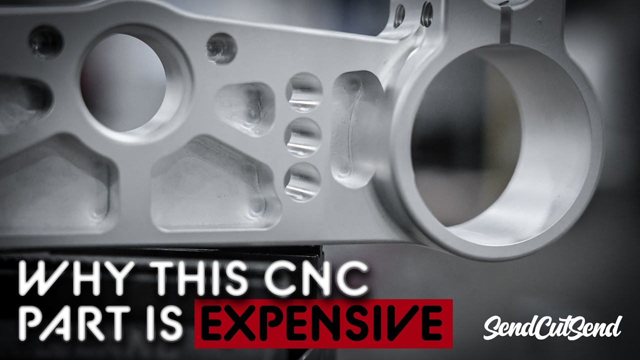
Designing parts for Computer Numerical Control (CNC) machining requires more than just high-level 3D modeling. To ensure your designs transition smoothly from CAD software to real-world production, implementing key Design for Manufacturability (DFM) principles is essential. Optimizing your parts for DFM helps minimize machining errors, cuts down manufacturing costs, and significantly speeds up production timelines.
Key Design Considerations for Precision CNC Milling
When engineering components for CNC milling and turning, subtle geometry details make a massive difference. Here are critical factors every engineer and designer should consider:
- Internal Corner Radii: Round cutting tools leave internal radii. Avoid sharp 90-degree internal vertical corners unless undercut features or special relief cuts are added.
- Cavity Depths & Pocket Wall Ratios: Excessively deep pockets require longer tools that are prone to chatter and deflection, compromising surface finish and dimensional tolerance.
- Wall Thickness: Extremely thin walls can deform under cutting pressure and thermal expansion. Maintaining uniform, robust wall dimensions ensures stability.
- Standard Tool Sizing: Aligning radii and hole diameters with standard tool dimensions avoids custom tooling expenses.
Watch: CNC Machining DFM Tips Explained
Gain deeper practical insights into CNC corner cutting techniques, tool selection, and smart feature positioning by watching this breakdown video:
Summary
By keeping practical manufacturing constraints in mind during the initial CAD modeling stage, you can substantially improve part quality while preventing costly redesigns. Applying effective DFM strategies ensures seamless communication with CNC machinists and yields optimal production results every time.


