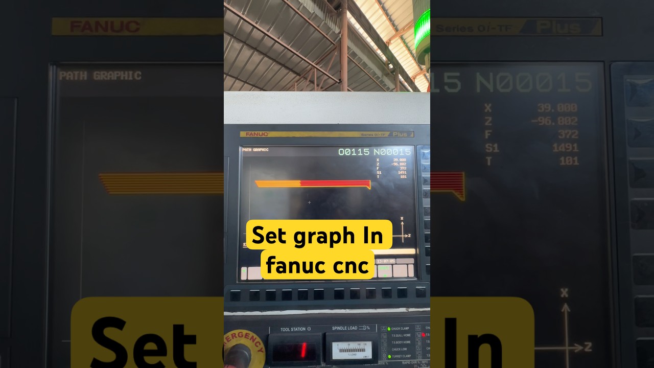
How to Easily Set Graphic Parameters on a Fanuc CNC Control
This article provides an in-depth exploration of CNC control, covering foundational concepts, practical applications, and engineering insights.
Visualizing your toolpath before running a program is one of the most effective ways to prevent costly tool breakage and machine collisions. Operating a modern CNC control requires precision, and utilizing built-in graphic simulation features gives operators the confidence that their code will run flawlessly.
If you are using a Fanuc system, setting the graph parameters correctly is essential for getting an accurate visual representation of your part geometry and cutting paths. Here is a quick guide on how to configure your graphic parameters step-by-step.
Why Graphic Parameter Setup Matters
Before a single chip is cut, configuring the graphic display on a Fanuc CNC control allows operators to verify tool movements, part dimensions, and coordinate origins. Without proper setup, the graphic screen may show the toolpath off-center, zoomed out too far, or completely out of frame, making visual verification impossible.
Step-by-Step: Configuring Graph Parameters
- Access the Graphic Screen: Press the
CUSTOM/GRAPHorGRAPHfunction key on your operator panel. - Navigate to Parameter Settings: Press the softkey labeled
[OPRT]and select[PARAM]or[G.PRM]to open the graphic parameter screen. - Define Coordinate Limits:
- Workpiece Center / Origin: Input the reference zero point (X, Y, and Z coordinates) based on your program's work offset (G54, G55, etc.).
- Display Range (Scale): Enter the dimensions of the stock material or display window size. Setting accurate minimum and maximum values ensures the toolpath fills the screen clearly. - Select Plane and View Mode: Choose the desired viewing angle—such as the standard 2D view (XY, ZX) or a dynamic 3D isometric projection.
- Execute Graphic Simulation: Switch the machine to
MEM(Memory) orEDITmode, enable theDRY RUNandMACHINE LOCKfunctions if necessary, and pressSTARTto simulate the path.
Best Practices for Smooth Verification
- Match Work Coordinates: Always ensure your graph parameters mirror your program's work coordinate system (WCS).
- Use Dry Runs for New Programs: Pair graphic checks with a dry run to confirm both syntax and physical travel limits.
Taking a couple of minutes to configure your visual settings ensures higher safety and accuracy on the shop floor. Mastering these basic functions on your CNC control will streamline your setup workflow and keep your machining operations running efficiently.
Visual Insights & Illustrations


