मेरे सभी Manufacturing Courses देखने के लिए नीचे दिए गए लिंक पर क्लिक करें: ...
मेरे सभी Manufacturing Courses देखने के लिए नीचे दिए गए लिंक पर क्लिक करें: ...
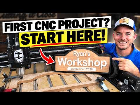
Stepping into the world of CNC (Computer Numerical Control) machining is an exhilarating milestone for any maker or hobbyist. The ability to transform a digital design into a physical masterpiece with surgical precision is nothing short of magic. However, that first time you stand before your machine can also feel a bit intimidating. To bridge the gap between "unboxing" and "creating," you need a solid plan and the right foundational knowledge.
Before you even turn on your machine, your project begins on the computer. For many beginners, software like Vectric provides the perfect entry point. This stage is where you define your workspace, import your vectors, and establish your toolpaths. Investing time in structured CNC training is crucial here; understanding the difference between a profile cut, a pocket cut, and a V-carve will save you hours of frustration and wasted material. Your software is the brain of the operation, and learning to speak its language is your first step toward success.
Once your design is ready, it’s time to move to the machine. Success in CNC work is often found in the details of the setup. You must ensure your material is securely fastened to the wasteboard—any movement during the cut can ruin the project or break a bit.
A standard beginner’s checklist should include: * Verifying your "Work Home" (X, Y, and Z zero points). * Checking that you have the correct bit installed for the specific toolpath. * Ensuring your dust collection is active and the path of the gantry is clear.
The moment of truth arrives when you hit the "Start" button. While the machine does the heavy lifting, your role is to observe. Through comprehensive CNC training, you learn how to listen to the machine—the sound of the spindle can tell you if your feed rates are too fast or if your bit is getting dull.
Don't be discouraged if your first project isn't perfect. Every broken bit and "oops" moment is a lesson in how the machine reacts to different materials and settings. By following a structured approach and prioritizing safety, you’ll quickly move from simple shapes to complex, professional-grade projects.
Starting your CNC journey is about more than just owning a tool; it’s about mastering a new craft. With the right resources and a bit of patience, you’ll be amazed at what you can create.

Designing complex 3D models for precision manufacturing often starts in CAD software like SolidWorks. If you are learning computer-aided design to prepare parts for machining, understanding fundamental 3D features is essential. In this practical CNC tutorial guide, we will explore the SolidWorks Swept Base/Boss feature and how it helps you build intricate, smooth geometry ideal for digital fabrication.
The Swept Base (or Swept Boss) feature allows designers to create 3D solids by driving a 2D profile sketch along a defined guide path. Unlike standard extrusions that only extend linearly, a sweep can follow complex curves, splines, and multi-directional trajectories. Whether you are modeling custom piping, ergonomic handles, or curved structural frames, mastering this tool is a vital step in any foundational CNC tutorial for 3D modeling.
Creating geometry in SolidWorks is only half the process; your model must also be easy to machine. When preparing your digital models as part of a complete CNC tutorial workflow, always consider cutting tool geometry:
By mastering the SolidWorks Swept Base feature with manufacturing in mind, you can seamlessly bridge the gap between initial digital concepts and physical CNC production. Practice creating different profiles and paths today to elevate your design capabilities!

When expanding a workshop or upgrading manufacturing operations, purchasing new equipment is a major milestone. However, many business owners make the mistake of focusing solely on initial purchase costs or basic cutting speeds. Selecting the right CNC device is ultimately about one critical metric: maximizing uptime. It is not just about cutting metal or acquiring hardware; it is about keeping your production line moving reliably every single day.
Before browsing manufacturer catalogs, step back and analyze the raw materials you process daily. The specific materials you work with determine the rigidity, spindle torque, speed, and tooling specifications required for your shop floor.
Machining lightweight aluminum requires vastly different capabilities than cutting titanium, stainless steel, or composites. By matching machine specs to your primary materials right from the start, you prevent tool chatter, reduce machine wear, and eliminate preventable operational bottlenecks.
It is easy to get distracted by advanced features, but operational stability is what drives long-term profitability. When evaluating a prospective CNC device, look past the marketing hype and focus on structural integrity, component reliability, and parts availability.
Unplanned downtime directly impacts your bottom line and damages client relationships. Look for machines designed with: * Thermal Stability: Prevents accuracy drift during long machining cycles. * Efficient Chip Evacuation: Keeps the work area clear and prevents tool breakage. * Maintainability: Provides easy access for routine servicing and preventative care.
Ultimately, acquiring machine tools should be viewed as a strategic capability upgrade rather than a simple hardware purchase. Investing in a reliable CNC device backed by strong vendor support ensures your shop remains productive, competitive, and profitable for years to come. Focus on material requirements and operational uptime to make the smartest decision for your business.

Have you ever wondered how modern aerospace components, medical implants, and automotive parts are created with pinpoint accuracy? Before the era of high-tech automation, skilled machinists spent countless hours manually adjusting levers and dials on lathes and milling machines. Everything changed with the dawn of computer numerical control. The CNC invention fundamentally transformed industrial production, bridging the gap between manual labor and automated precision.
In the mid-20th century, post-WWII manufacturing demanded faster, more reliable ways to produce complex aircraft parts and helicopter rotor blades. In the late 1940s, John T. Parsons, partnering with researchers at the Massachusetts Institute of Technology (MIT), pioneered the concept of Numerical Control (NC).
By converting complex mathematical coordinates into punched paper tape, machines could follow exact instructions without direct human intervention. This landmark advancement laid the critical groundwork for the official CNC invention when microprocessors emerged in the 1970s, replacing physical paper tapes with digital memory and programming languages like G-code.
Integrating digital computers directly into machining units unleashed unprecedented efficiency. Operators could now program complex toolpaths, store multiple designs in memory, and tweak cutting parameters directly on machine interfaces.
Modern multi-axis CNC mills, lathes, and plasma cutters operate continuously with minimal oversight. They deliver tolerances measured in micrometers, allowing factories across the globe to mass-produce intricate components with zero variation from part to part.
The evolution of machining hasn't slowed down. Today's industrial revolution is combining traditional CNC systems with Artificial Intelligence (AI) and the Internet of Things (IoT). Modern AI-powered CNC systems analyze real-time sensor data to optimize spindle speeds, monitor tool wear, and prevent thermal distortion before defects occur.
The journey from hand-cranked tools to self-optimizing machinery highlights the profound impact of the CNC invention. As AI continues to push the boundaries of modern engineering, CNC technology will remain the essential backbone of global manufacturing—shaping the future one precise cut at a time.
This article provides an in-depth exploration of CNC system, covering foundational concepts, practical applications, and engineering insights.
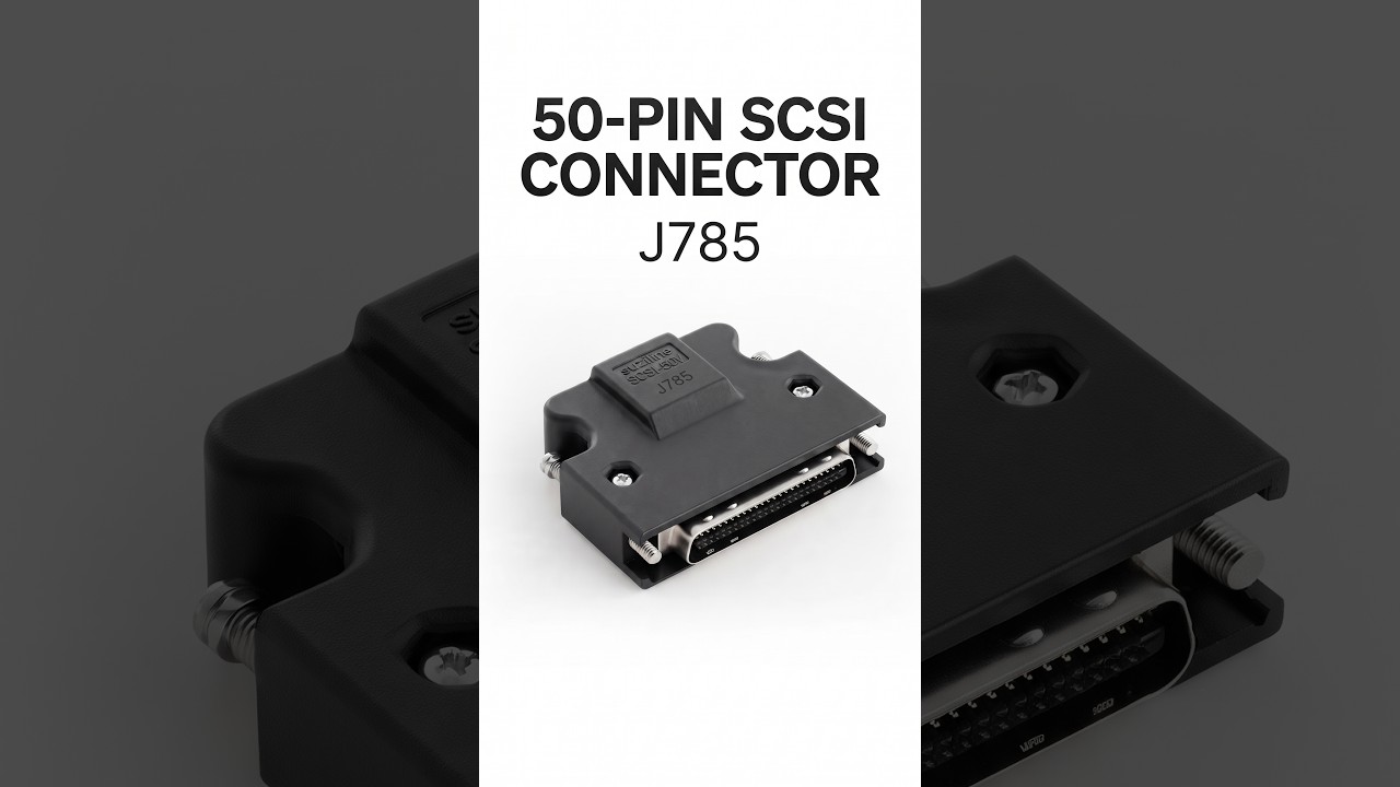
When building or upgrading a precision machine, signal integrity and robust hardware connections are critical. The J785 50-Pin SCSI Male Connector Jack with Protective Hood stands out as an essential component for custom control wiring. Specifically designed to handle the complex signal demands of modern industrial automation, this heavy-duty connector ensures smooth communication between control units, stepper drives, and servo motors in your modern CNC system.
The J785 connector is tailored for high-density wiring environments where reliability cannot be compromised. Its key highlights include:
Modern motion control systems rely heavily on fast, accurate feedback signals to maintain micro-inch precision. A poor wiring connection can lead to signal dropouts, position errors, or costly operational downtime. By integrating the J785 connector into your CNC system, you guarantee a stable signal path for encoder feedback, pulse/direction inputs, and critical I/O communication. The protective hood further safeguards delicate control lines from ambient factory noise.
Whether you are retrofitting older machinery, assembling a custom control box, or performing routine industrial maintenance, the J785 SCSI connector simplifies the wiring process. It is widely utilized across various industrial setups, including:
Investing in high-quality interconnect hardware like the J785 50-Pin SCSI Male Connector is essential to building a resilient, accurate CNC system. With its rugged protective hood and high-pin-count design, it delivers the long-term stability and signal protection required for flawless industrial performance.

Precision is the backbone of modern manufacturing, and operating CNC machinery efficiently requires a deep understanding of machine offsets. Whether you are a beginner operator or an experienced programmer, setting tool offsets and work offsets accurately is essential for preventing machine crashes, minimizing tool wear, and producing precise parts.
In this guide, we will break down the fundamentals of setting Work Offsets and Tool Offsets to help you optimize your machining workflow.
A Work Offset (commonly referenced by G54 through G59 G-codes) establishes the relationship between the machine's absolute home position and the reference zero point on your workpiece. When setting up CNC machinery, the control system must know precisely where the raw material is clamped on the table or chuck.
By touching off your stock along the X, Y, and Z axes, you establish a Work Coordinate System (WCS). This ensures that your CNC program runs accurately relative to the actual part rather than the physical machine limits.
While work offsets define the workpiece location, tool offsets account for the dimensions and physical variations of each cutting tool in your magazine.
To maintain safety and high precision when operating CNC machinery, follow these best practices:
Mastering tool and work offsets is a fundamental skill that turns G-code instructions into perfect physical components. By consistently applying proper offset measurement techniques, you ensure part quality, extend tool life, and maximize the efficiency of your equipment.

In the competitive world of industrial manufacturing, the ability to produce high-tolerance components with speed and repeatable accuracy is what defines a successful operation. Metalworking has evolved from labor-intensive manual processes into a high-tech discipline where digital software meets raw mechanical power. At the center of this transformation is the CNC machine, a tool that has become the vital backbone of modern engineering workshops worldwide.
Modern metalworking encompasses a wide range of specialized techniques, including turning, drilling, and milling. In the past, each of these tasks required separate manual setups and significant human intervention, which increased the risk of error and material waste. Today, a sophisticated CNC machine can handle these diverse operations with ease and extreme fluidity.
By automating the movement of cutting tools across multiple axes, these machines ensure that every hole drilled and every surface milled is perfectly aligned with the original digital blueprint. This level of precision is essential for industries like aerospace and automotive engineering, where even a single millimeter of deviation can lead to mechanical failure.
True success in the workshop is a combination of technical skill and the right equipment. To achieve high-quality results, operators must focus on the "strength" of their process—ensuring that the machinery can handle heavy-duty metal processing without sacrificing finesse. Professional tips often emphasize the importance of cooling systems and toolpath optimization to extend the life of the equipment.
When you master the specific settings of your CNC machine, you unlock the potential to produce complex geometries that were once thought impossible. This capability allows small workshops to compete with larger factories, giving them a significant edge in a demanding global market.
For those looking to elevate their production, consistency is key. Regular maintenance, staying updated with the latest CAD/CAM software, and choosing the right cutting bits for specific metals are all vital components of a productive environment. Whether you are a seasoned machinist or just starting out, understanding the synergy between human expertise and automated technology is the fastest path to growth. By embracing these advanced tools, you ensure that your workshop remains a hub of innovation, strength, and high-quality craftsmanship.
This article provides an in-depth exploration of CNC info, covering foundational concepts, practical applications, and engineering insights.
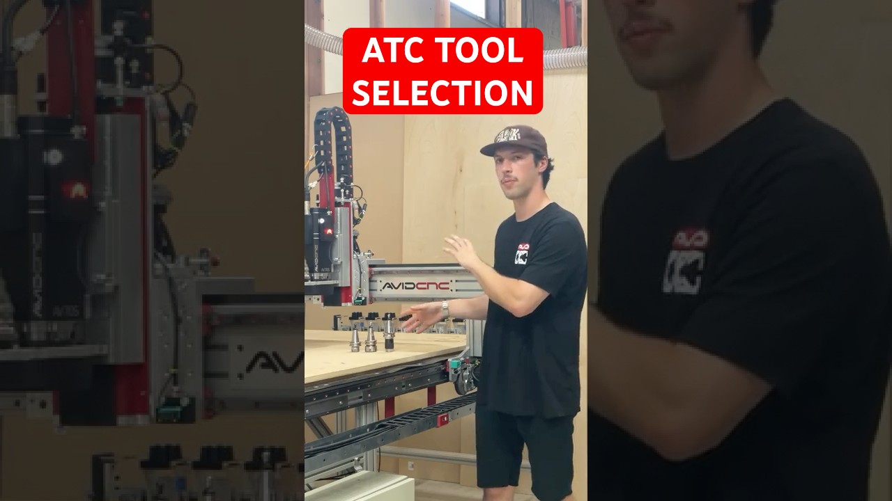
In the fast-paced world of digital fabrication, efficiency and precision are paramount. Whether you are running a commercial woodworking shop or pushing the boundaries of rapid prototyping, upgrading your machine with an Automatic Tool Changer (ATC) is one of the most effective ways to supercharge your productivity. Having access to reliable CNC info regarding tooling selection and automated tool racks can make all the difference in streamlining your manufacturing process.
Choosing the right tooling for an ATC system goes beyond simply picking sharp router bits. It requires a clear understanding of tool holders, collets, and how different bit geometries interact with your machine’s spindle. Proper ATC tooling ensures smooth, automated bit changes without operator intervention, significantly reducing human error and eliminating costly downtime.
When evaluating your tooling setup, pay close attention to concentricity and weight distribution. High-RPM spindles demand balanced tool holders (such as ISO or BT standards) to minimize vibration, deliver clean cut finishes, and protect your spindle bearings from unnecessary wear.
Automating your router is only as reliable as the rack holding your cutters. Recent developments in prototype tool rack design focus on maximum stability, dust protection, and reliable actuation. Seeing a prototype tool rack in action offers valuable CNC info on how modern sensor integration and mechanical locks keep tools secure during high-speed operations.
A well-engineered tool rack ensures that tool change commands are executed seamlessly every time. By shielding unused tool holders from flying chips and fine dust, advanced tool racks keep your tapered connections clean, preventing alignment issues and maintaining precision throughout complex, multi-tool job runs.
Integrating an ATC into your CNC router is a transformative leap forward. Instead of manually pausing jobs and recalibrating Z-axis zeroes for every tool swap, an automated system executes multi-stage cutting, drilling, and carving programs effortlessly. For makers and machinists seeking up-to-date CNC info, staying informed on emerging ATC prototypes and tooling strategies provides a clear roadmap toward a smarter, more profitable workshop.

Transforming your home into an automated haven doesn't stop at smart lights and voice assistants. One of the most practical and satisfying DIY projects you can tackle is creating a smart bed integrated with Home Assistant. From automatic sleep tracking and soft under-bed nightlights to triggering whole-house "Goodnight" routines the moment you lie down, a smart bed adds incredible convenience to your daily routine.
Building a reliable smart bed requires sturdy, custom-fit hardware components to hold your sensors securely under the bed frame. To house strain gauges, load cells, or wiring cleanly, high-precision manufacturing is essential. By utilizing Smart CNC machining services, you can design and craft durable aluminum or hardwood mounting brackets tailored exactly to your bed frame's dimensions. Combining custom 3D printing with Smart CNC fabricated parts ensures that your presence sensors stay accurately aligned without compromising the aesthetic or structural integrity of your bed.
Once your physical mounts are installed, the next step involves the electronics. Bed occupancy detection typically relies on pressure sensors connected to a micro-controller like an ESP32 running ESPHome. For a clean setup, designing a custom PCB simplifies the wiring, making it both compact and reliable. Fabrication services like PCBWay offer seamless prototyping for custom circuit boards, CNC parts, and enclosures, helping your DIY project achieve a polished, commercial-grade finish.
With the hardware configured, flash your microcontroller and link it to your Home Assistant server. Once integrated, Home Assistant can immediately detect when you get into or out of bed. This opens up endless automation possibilities: - Automatically turn off all house lights and lock the front door when both sides of the bed are occupied after 10 PM. - Slowly illuminate soft footwell lighting if you get up during the night. - Adjust your smart thermostat to your ideal sleeping temperature as soon as you settle in.
By leveraging open-source automation alongside modern Smart CNC fabrication tools, turning your standard mattress into an intelligent, modern sleeping sanctuary is easier and more precise than ever.
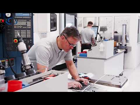
In the fast-paced world of modern manufacturing, downtime is the ultimate enemy of profitability. Whether you are a small job shop or a large-scale production facility, the ability to quickly find, configure, and utilize the right cutting tools is critical to staying competitive. This is where Machining cloud steps in as a game-changer for digital tool management.
Traditionally, searching for the perfect tool involved flipping through massive paper catalogs or navigating multiple manufacturer websites. This process was not only time-consuming but also prone to manual data entry errors. By leveraging the power of Machining cloud, engineers and programmers can access a centralized hub containing up-to-date data from the world’s leading tool manufacturers.
The platform allows users to find the exact tools they need, build 3D assemblies, and instantly download the digital twins required for CAD/CAM programming. This ensures that the data you are using in your simulation matches the physical tool on the shop floor, drastically reducing the risk of costly collisions and setup errors.
The core mission of any high-end tool management system is to increase machine uptime. When your programmers spend less time hunting for technical specifications and more time optimizing paths, your machines stay running longer. By integrating Machining cloud into your workflow, you eliminate the "data gap" between the tool manufacturer and your CNC machine.
With accurate 3D models and cutting data available at your fingertips, the transition from the office to the spindle becomes seamless. This digital continuity ensures that your shop operates with high precision, allowing for faster turnaround times on complex projects.
As the industry moves further into the era of smart manufacturing, digital data accessibility is no longer optional—it is a necessity. This platform provides the infrastructure needed to support a fully digital workflow. It bridges the gap between software and hardware, providing a reliable source of truth for tool geometries, speeds, and feeds.
If you are looking to take your shop's efficiency to the next level, it is time to move away from outdated manual processes. Embracing a digital-first approach to tool management will not only save you time today but will also position your business for long-term success in an increasingly automated world.

Are you planning to launch a career in data analytics? With dozens of popular platforms—such as Codebasics, PW Skills, Internshala, Simplilearn, and Odin School—competing for your attention, choosing the right course can feel overwhelming. Before investing your hard-earned money, it is crucial to understand which program actually delivers job-ready skills and real-world value.
Each training provider caters to a different learning style and budget:
A high-quality data analytics curriculum does more than just teach basic SQL queries and Excel formulas. To stand out in today's competitive job market, you need experience managing complex, unstructured, and domain-specific datasets. For example, analyzing specialized industrial G-code data from manufacturing automation requires advanced logic, structured data pipelines, and strong Python skills.
Courses that challenge you with real-world scenarios—ranging from e-commerce user behavior to automated G-code data streams—prepare you far better for actual workplace demands than platforms relying solely on basic boilerplate projects.
Before enrolling, carefully evaluate each platform's project variety, instructor experience, and career support services. Make sure the curriculum covers end-to-end data processing for modern formats, including IoT logs, financial metrics, and G-code data models. Selecting a program that balances affordability with practical, hands-on application ensures you get the maximum return on your educational investment.
This article provides an in-depth exploration of Smart CNC, covering foundational concepts, practical applications, and engineering insights.
Precision is the backbone of modern manufacturing. When it comes to thread turning on a lathe, selecting the right insert geometry can make or break your finish quality and overall tool longevity. Among the most popular tooling choices in modern machine shops are IR and ER indexable inserts. Understanding how these tools function within a modern Smart CNC environment helps machinists maximize efficiency while maintaining tight tolerances.
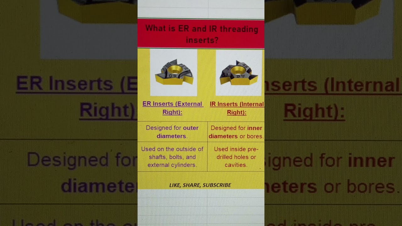
In indexable tooling systems, standardized letter codes define the specific application and direction of the cutting edge:
While IR and ER inserts may look similar at first glance, their clearance angles, cutting edge orientations, and chip breaker geometries are distinct. Using an ER insert for internal threading (or vice versa) leads to poor surface finishes, rapid tool wear, or catastrophic tool breakage.
Integrating the correct threading insert into a Smart CNC setup ensures optimal chip evacuation and prevents chatter during the threading cycle. Internal threading (IR) demands careful clearance consideration to avoid tool rubbing against the bore wall, whereas external threading (ER) requires maximum tool rigidity to handle higher cutting forces.
Using high-grade carbide IR and ER inserts allows machinists to achieve precise thread profiles, minimize cycle times, and reduce manual intervention—core principles of automated, high-precision manufacturing.
By incorporating Smart CNC practices and selecting the correct ER or IR insert for your specific application, you can significantly extend tool life, achieve mirror-like thread finishes, and boost shop floor productivity.
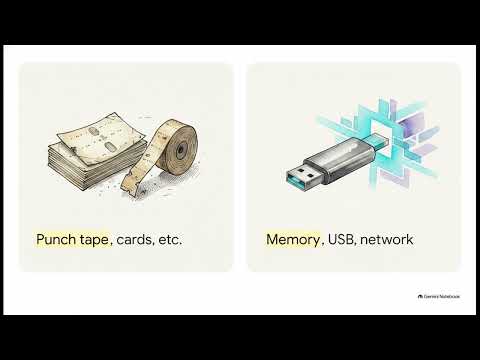
In modern manufacturing, precision and speed are paramount. Over the decades, automated machining has evolved from simple punch-card hardware to sophisticated network-driven environments. To understand where industrial automation stands today, it is essential to look at the three pillars of numerical control: NC, CNC, and DNC.
Numerical Control (NC) machines were the pioneers of automated manufacturing. They relied on hardwired logic and physical mediums like punched paper tapes to execute machining instructions. While revolutionary at the time, NC machines lacked flexibility—changing a part design meant manually recreating the entire physical tape.
Computer Numerical Control (CNC) solved this limitation by embedding a dedicated microcomputer into the machine tool. Operators could edit programs directly at the machine console, store multiple instruction sets, and execute complex toolpaths with unprecedented accuracy. However, managing file storage and transferring large G-code files to individual machines individually remained a major bottleneck.
This is where a DNC system (Direct or Distributed Numerical Control) comes into play. Rather than treating each machine as an isolated island, it links multiple CNC tools to a central server or workstation over a local network.
In a modern smart shop, a central DNC system manages program storage, file transfers, and revision control seamlessly. Instead of machinists manually carrying USB drives or using legacy RS-232 serial cables for every job, the central server streams G-code directly to each machine on the shop floor. If a file is too large for an older machine's internal memory, the server feeds the instructions in real time—a process known as drip-feeding—ensuring continuous operation without hardware upgrades.
While NC laid the foundation and CNC brought intelligence to individual machine tools, implementing a reliable DNC system is the key to unifying your entire workshop floor. By connecting design software directly to operational machinery, modern plants achieve maximum productivity, fewer errors, and complete process control.

Operating a CNC machine efficiently requires more than just high-quality hardware; it demands the right software configuration and real-time operational oversight. If you are using LinuxCNC, knowing how to choose the right setup and monitor your stock materials effectively can make all the difference in your production speed and output quality.
In this practical guide, we break down how to compare your CNC options and set up a reliable workflow tailored to your specific machining needs.
When working with LinuxCNC, tracking machine coordinates, feed rates, and stock dimensions in real time is vital. Implementing an intuitive CNC monitor interface allows machinists to keep a close eye on tool paths and raw materials throughout the execution process.
By utilizing a dedicated CNC monitor, you reduce setup errors, prevent costly collisions, and ensure that your programmed cut lines match the actual physical stock on your machine bed. This real-time visibility transforms complex G-code execution into a predictable, manageable process.
Selecting the right CNC plan or configuration depends heavily on your project requirements and machine capabilities. Here are the main elements to compare before launching your next job:
To get the best practical results from your setup, pair proper planning with live tracking tools. A robust CNC monitor gives you immediate feedback on spindle load, position offsets, and execution progress, empowering you to make necessary adjustments on the fly.
Taking the time to evaluate your LinuxCNC options will help you optimize job execution, minimize material waste, and streamline your entire shop floor workflow.
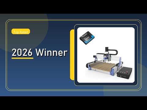
Whether you are a seasoned woodworker, an enthusiastic hobbyist, or an aspiring maker, finding the right desktop router machine can dramatically transform your workshop capabilities. The Genmitsu PROVerXL 4030 V2 has taken the maker community by storm, offering an impressive blend of structural rigidity, cutting power, and modern features. In this review, we take an honest look at how this machine stands out and why its updated CNC control capabilities set a new benchmark for desktop machining.
The Genmitsu PROVerXL 4030 V2 isn't just a minor incremental update—it is a serious machine built for accurate routing. Featuring redesigned aluminum extrusions, upgraded dust protection, and sturdy linear rails, the V2 delivers remarkable stability during intense milling operations. Whether you are working with softwoods, hardwoods, acrylics, or aluminum, this machine maintains clean cuts without losing steps or sacrificing accuracy.
One of the standout features of the PROVerXL 4030 V2 is its integrated offline control module equipped with a sleek LCD touchscreen. Gone are the days when you needed a dedicated laptop tethered to your router in a dusty workshop environment. This setup simplifies your workflow by offering direct CNC control right at your fingertips. From zeroing axes and adjusting feed rates to running G-code files straight from a memory card, the user interface makes navigation smooth and intuitive for beginners and experts alike.
Beyond its default cutting volume, the PROVerXL 4030 V2 offers exceptional modularity. Makers looking to expand their workspace can easily upgrade the frame with extension kits. Additionally, the improved control board ensures compatibility with various spindle upgrades and laser modules, giving you complete CNC control over an ever-growing list of creative projects.
The Genmitsu PROVerXL 4030 V2 delivers outstanding value for anyone seeking high performance without the industrial price tag. With its robust construction, user-friendly offline interface, and expandable framework, it provides an unbeatable routing experience that empowers makers to bring complex designs to life effortlessly.
This article provides an in-depth exploration of Machining cloud, covering foundational concepts, practical applications, and engineering insights.
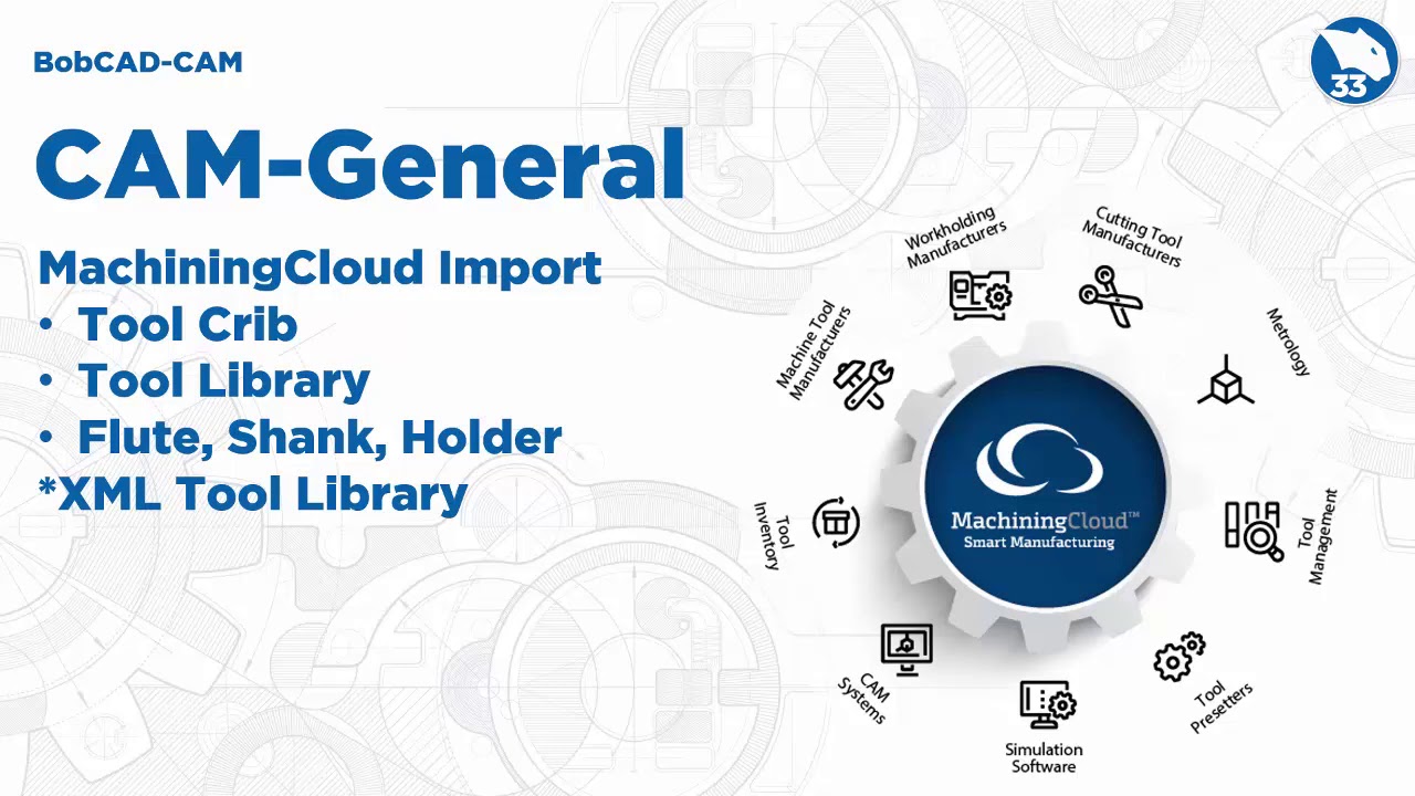
In the fast-paced world of CNC manufacturing, efficiency and accuracy in tool management are essential for maintaining a competitive edge. Manually defining complex tool geometries and cutting parameters within your software can be time-consuming and prone to costly human errors. Fortunately, BobCAD-CAM V33 introduces a revolutionary solution designed to simplify this process through seamless integration with Machining cloud.
BobCAD-CAM V33 makes history as the first release ever to offer a direct method for bringing tool assembly exports from the Machining cloud platform straight into your CAM workspace. Instead of spending hours building custom tool models from scratch or manually hunting down manufacturer specifications, programmers can now leverage a centralized digital catalog.
This powerful feature connects you directly with leading tool manufacturers, allowing you to access real-time tool data, exact 3D models, and recommended cutting parameters with unprecedented ease.
By incorporating modern digital tooling workflows into BobCAD-CAM V33, machine shops can experience immediate operational improvements:
Leveraging the power of the Machining cloud within BobCAD-CAM V33 gives CNC programmers and shop managers the tools they need to maximize shop-floor productivity. By automating the tool data import process, you can minimize machine downtime, extend tool life, and ensure consistent part quality across every job.

In the fast-paced world of modern manufacturing, precision and speed are critical. Whether you are operating 3-axis mills or complex 5-axis machinery, leveraging top-tier CNC software is the key to maximizing shop floor productivity and reducing cycle times. Among the leading solutions available today, Autodesk PowerMill stands out as an industry heavyweight for high-speed and multi-axis programming.
If you are new to automated toolpath generation, getting started might feel overwhelming. However, mastering the fundamentals of PowerMill can drastically elevate your programming capabilities and streamline your entire machining workflow.
Autodesk PowerMill is engineered specifically for complex components, molds, and dies. Unlike basic CAM packages, advanced CNC software like PowerMill offers specialized toolpath strategies designed to minimize tool wear, enhance surface finishes, and optimize cutting efficiency.
Key advantages include: * High-Speed Machining (HSM): Smooth toolpath transitions maintain high feed rates while protecting your cutting tools. * 5-Axis Capability: Superior control over tool axis orientation allows efficient machining of deep cavities and complex geometries. * Safety & Simulation: Comprehensive stock simulation and collision detection keep your physical setup safe from costly crashes.
To generate your first error-free program, follow this straightforward workflow:
Transitioning to industry-standard CNC software requires practice, but the payoff in speed, surface quality, and part accuracy is immense. By learning the core features of Autodesk PowerMill, you take a major step toward optimizing your manufacturing operations and advancing your technical skills. Start practicing with basic geometries today to build confidence for complex multi-axis projects tomorrow!
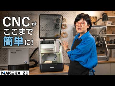
Desktop manufacturing has evolved dramatically, bringing industrial-grade capabilities directly to your home workbench or small studio. Enter the Makera Z1, a next-generation desktop CNC router designed to bridge the gap between digital design and physical prototyping. Whether you work with aluminum, brass, wood, or acrylic, this compact powerhouse allows makers and engineers to transform complex CNC data into beautifully carved physical objects with incredible precision.
Right out of the box, the Makera Z1 impresses with its sleek build and user-friendly setup. Unlike traditional, bulky industrial machines, the Z1 fits comfortably on a standard desk while maintaining the rigidity required to cut through tough materials.
One of its most impressive highlights is multi-material versatility. It is not limited to soft woods or plastics; the Z1 handles non-ferrous metals like aluminum and brass effortlessly. This makes it an ideal solution for prototyping mechanical components, custom hardware, personalized signs, and intricate artistic projects.
What truly sets the Makera Z1 apart is its streamlined workflow. Creators no longer need to spend endless hours manually configuring tedious toolpaths. By preparing your 3D models in your CAD/CAM software of choice, you can export optimized CNC data straight to the machine. The Z1 interprets these instructions smoothly, executing ultra-precise cuts, carves, and engravings directly from your digital files.
This seamless integration ensures high repeatability and accuracy, allowing you to produce professional-quality parts without needing years of traditional machining experience.
The Makera Z1 represents a major leap forward in personal fabrication. By simplifying the process of executing digital CNC data, it empowers creators, hobbyists, and professional engineers to turn their imaginative 3D concepts into tangible metal and wood reality. If you are looking for an ultimate, high-performance desktop CNC router to elevate your workshop, the Makera Z1 is definitely worth a close look.

In the world of modern manufacturing, precision and reliability are paramount. Investing in a high-performance CNC system can transform your shop floor efficiency, but maintaining that peak performance requires ongoing care. Among all maintenance routines, one often overlooked factor stands out as crucial: proper lubrication.
Failing to adequately lubricate your machinery can lead to severe operational consequences, reducing equipment lifespan and hurting your bottom line.
When linear guides, ball screws, and spindles operate without sufficient oil or grease, metal-on-metal friction increases dramatically. This friction generates excess heat, causing rapid wear and tear on sensitive components. Over time, subtle misalignments occur, degrading cutting accuracy and surface finish quality.
Inadequate lubrication directly leads to: - Accelerated Component Wear: Friction destroys precision components long before their expected service life. - Unplanned Machine Downtime: Sudden breakdowns force immediate halts in production schedules. - Escalating Repair Expenses: Replacing damaged spindles or ball screws is far more expensive than routine preventive care.
Downtime is the enemy of productivity. A sudden mechanical failure caused by friction doesn't just stop a single job—it disrupts your entire production workflow and delivery timelines. Neglecting routine maintenance can severely compromise your entire CNC system, leading to thousands of dollars in lost revenue and emergency repair costs.
By establishing a consistent lubrication routine, you minimize thermal expansion, prevent corrosion, and ensure smooth axis movements. Whether your setup utilizes manual greasing points or an automated central lubrication unit, using the manufacturer-recommended lubricants at specified intervals is essential.
To keep your equipment running smoothly: 1. Follow Guidelines: Always use the recommended viscosity and type of grease or oil specified by the manufacturer. 2. Inspect Automated Lubricators: Periodically check reservoir levels and verify that distribution lines are clear of air bubbles and blockages. 3. Maintain a Strict Schedule: Don't wait for grinding noises or thermal alerts to apply fresh lubricant.
Proper lubrication isn't just a minor task on a maintenance checklist; it is a vital defense against premature wear and costly operational halts. By prioritizing routine maintenance, you safeguard your operational efficiency and ensure your CNC system delivers accurate, reliable performance for years to come.