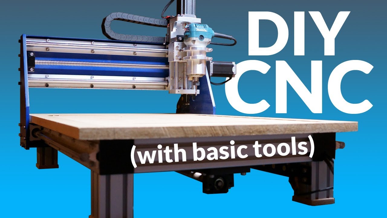
Introduction to CNC Machining and the Power of DIY
CNC stands for Computer Numeric Control. In basic terms, it is a milling machine operated by a computer that drives motors to execute precise and highly repeatable machining operations. Compared to standard human handiwork, a CNC machine is capable of movements that are far more accurate, rigid, and consistent. By interpreting digital instructions known as G-code, stepper motors move the cutting tool across three or more axes (X, Y, and Z) to precisely shape various materials.
While industrial or pre-built desktop CNC machines can be incredibly expensive or lack the rigid structure required for heavy-duty tasks, building your own DIY CNC router allows you to customize the dimensions, ensure maximum rigidity, and optimize the overall performance within a reasonable budget.
Key Engineering Principles: Rigidity and Component Selection
When designing a reliable CNC router, power and structural rigidity are the two most critical factors. High rigidity ensures the machine can cut through hard wood or even light-duty aluminum without vibrating or losing precision. To achieve this, several key structural design choices must be implemented:
- Screw-Driven System: Utilizing ball screws instead of belt-driven systems provides significantly higher torque, precision, and zero backlash under heavy loads.
- Supported Linear Rails: Implementing heavy-duty supported linear rails on the X and Y axes provides smooth lateral movements while effectively handling mechanical stress.
- Aluminum Extrusions and Solid Plates: Constructing the main frame with 6060 aluminum extrusions offers a lightweight yet rigid foundation. Crucial structural parts, such as the Gantry side plates, should be machined from solid aluminum plates (e.g., 3/8-inch or 1/2-inch thickness) to maintain vertical alignment.
- Spindle Selection: A reliable and widely available router, such as the Makita RT0701C, serves as an excellent affordable spindle option for desktop setups.
The Mechanical and Electronic Assembly Process
Building a CNC router from scratch involves precise manual crafting and accurate electronics wiring. Here is the step-by-step breakdown of the assembly framework:
1. Mechanical Fabrication and CAD Design
Before buying components, using a CAD program like Autodesk Fusion 360 allows you to model every dimension accurately. Once the 800mm rails for the y-axis and 600mm rails for the x-axis are aligned, the solid aluminum plates must be cut, drilled, and tapped using metric M5/M6 bolts and t-slot nuts. A replaceable MDF spoil board is then mounted on top of the mainframe and flattened using a facing bit to ensure it remains perfectly parallel to the cutting tool.
2. Motor Integration and Electronic Control Box
To drive the lateral motion systems, high-torque Nema 23 stepper motors (e.g., 425 oz-in) are paired with dedicated stepper drivers and a 36-volt power supply unit. An Arduino Uno running open-source GRBL firmware functions as the primary intermediary control board, converting signals from the computer into physical pulse/direction steps for the motors.
3. Reducing Signal Noise and Wire Management
One major issue during heavy machining is electromagnetic interference (EMI). It is highly recommended to use shielded microphone cables for all motor and limit switch lines to prevent false positives that can trigger random emergency stops. Organizing these cables inside dynamic drag chains protects the wiring from entering the toolpath of the spinning router bit.
Testing, Tuning, and Enclosure Additions
Once the electronics are enclosed and the firmware is properly configured via software like Universal Gcode Sender (UGS), initial calibration involves running basic 2D letter carves before attempting complex 3D wood modeling. Additionally, building a dedicated acrylic and wooden enclosure is vital. The enclosure successfully contains wood dust and aluminum chips from creating a massive mess while significantly dampening the loud acoustic noise produced by the spindle motor.
...


